���@USB�ʐM2 �@�@�@�@�@�@�@�@�@�@�@�@�@�@�@�@�@�@�@�@�@�@�@�@�@�@�@
 �@�@
�@�@
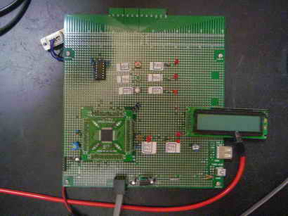
�@�@���@PIC18F14K50�@HID�N���X�@LED �_��/�������䁕�\��
�@�@�@
�@�@
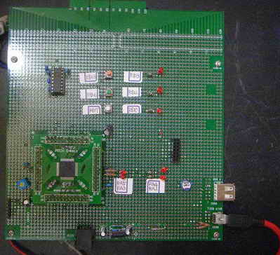
�@������i�d�l��
�@�@�EPC�iWindows)��̃{�^���X�C�b�`�~4���N���b�N����Ɓ@PIC18F40K50�̃L�o����̑Ή�����LED��ON/OFF���邱��
�@�@�EPC��PIC�Ԃ�USB�ʐM��HID�N���X�Ƃ���B
�@�@�E�{�^���X�C�b�`��LED��ON���Ă���Ƃ��͐ԐF�AOFF�̎��͊D�F�Ƃ���B
�@�@�EUSB�ʐMON�̃{�^���{�^���X�C�b�`���t�H�[����ɂ������邱�ƁB�@�܂�USB�ʐM���m��������h�ڑ������I�h�̕������e�L�X�g�{�b�N�X�ɕ\���̂���
�@���@PC���̃\�t�g�iWindows)�́@���������Q�Ɗ肢�܂��@
�@�@�@
������i��H�}��(����H�}��PDF�t�@�C���j
 �@
�@
������i�O�ρ����L�̎ʐ^�ɂ͏�L��H�}�ɂ͂Ȃ��A�܂��{�e�[�}�ƊW�̂Ȃ����i�����X�ʂ��Ă��܂�
�@ �@�@�@�@
�@�@�@�@�@�@�@�@�@�@
�@���v���O�����၄
//Ledx4 �I���I�t����
//PIC18F14K50
#include "usb.h"
#include "HardwareProfile.h"
#include "usb_function_hid.h"
//�V�X�e���N���b�N48MH���i= 12MHz x 4PLL)
#pragma config CPUDIV = NOCLKDIV ,USBDIV = OFF, PCLKEN = ON
#pragma config FOSC = HS, PLLEN = ON, HFOFST = OFF
#pragma config PWRTEN = ON, BOREN = OFF, MCLRE = OFF, BORV = 30
#pragma config WDTEN = OFF, LVP = OFF, FCMEN = OFF, IESO = OFF
#pragma config CP0 = OFF, XINST = OFF
// USB�֘A�o�b�t�@�A�ϐ���`
#pragma udata usbram2
unsigned char ReceivedDataBuffer[64];
unsigned char SendBuf[64];
#pragma udata
USB_HANDLE USBOutHandle = 0;
USB_HANDLE USBInHandle = 0;
BOOL blinkStatusValid = TRUE;
//�O���[�o���ϐ���`
BYTE counter;
BOOL blinkStatusValid;
//�R�}���h�萔��`
typedef enum
{
CHECK = 0x30,
POUT = 0x31,
PIN = 0x32,
AIN = 0x33,
RESET = 0xFF
}TYPE_CMD;
void BlinkUSBStatus(void);
void ProcessIO(void);
void YourHighPriorityISRCode();
void YourLowPriorityISRCode();
void USBCBSendResume(void);
// ���荞�݃x�N�^��`
#pragma code REMAPPED_HIGH_INTERRUPT_VECTOR = 0x08
void Remapped_High_ISR (void)
{
_asm goto YourHighPriorityISRCode _endasm
}
#pragma code REMAPPED_LOW_INTERRUPT_VECTOR = 0x18
void Remapped_Low_ISR (void)
{
_asm goto YourLowPriorityISRCode _endasm
}
// ���荞�ݏ�����
#pragma code
#pragma interrupt YourHighPriorityISRCode
void YourHighPriorityISRCode()
{
USBDeviceTasks();
}
#pragma interruptlow YourLowPriorityISRCode
void YourLowPriorityISRCode()
{
}
#pragma code
void main(void)
{
ANSEL = 0x00; // �f�W�^���ɐݒ�
TRISC = 0; //LED�|�[�g�iRC0-RC3) �Fout
LATC = 0; //�SLED����
//USB�֘A
USBDeviceInit(); // USB������
USBInHandle = 0;
USBOutHandle = 0;
blinkStatusValid = TRUE; // USB�ڈ�LED�L����
USBDeviceAttach(); // USB���荞�ݗL����
while(1)
{
//USB�ڑ����Ȃ瑗��M���s
if((USBDeviceState >= CONFIGURED_STATE)&&(USBSuspendControl!=1))
ProcessIO(); // �R�}���h���s
}
}
//���[�U�[�A�v���̓��o�͏�����
void ProcessIO(void)
{
//�f�[�^��M����
if(!HIDRxHandleBusy(USBOutHandle))
{
blinkStatusValid = FALSE;
SendBuf[0] = ReceivedDataBuffer[0];
SendBuf[1] = ReceivedDataBuffer[1];
//�R�}���h�̏���
switch(ReceivedDataBuffer[0]) // �R�}���h�R�[�h�`�F�b�N //��M�f�[�^�̐擪�o�C�g�`�F�b�N
{
//�ڑ��m�F����
case CHECK: //0x30
SendBuf[2] = 'O';
SendBuf[3] = 'K';
if(!HIDTxHandleBusy(USBInHandle))
USBInHandle = HIDTxPacket(HID_EP,(BYTE*)&SendBuf[0],64);
break;
//LED����̏ꍇ
case POUT: //0x31,
if(ReceivedDataBuffer[1] == 0x31){ //LED0�̏ꍇ
if(ReceivedDataBuffer[2] == 0x31)
{ mLED_1_On(); } //LED�FON
else if(ReceivedDataBuffer[2] == 0x30)
{ mLED_1_Off(); } //LED�FOFF
SendBuf[2] = mLED_1 + 0x30;
}
else if(ReceivedDataBuffer[1] == 0x32){ //LED1�̏ꍇ
if(ReceivedDataBuffer[2] == 0x31)
{ mLED_2_On(); }
else if(ReceivedDataBuffer[2] == 0x30)
{ mLED_2_Off(); }
SendBuf[2] = mLED_2 + 0x30;
}
else if(ReceivedDataBuffer[1] == 0x33){ //LED�Q�̏ꍇ
if(ReceivedDataBuffer[2] == 0x31)
{ mLED_3_On(); }
else if(ReceivedDataBuffer[2] == 0x30)
{ mLED_3_Off(); }
SendBuf[2] = mLED_3 + 0x30;
}
else if(ReceivedDataBuffer[1] == 0x34){ //LED�R�̏ꍇ
if(ReceivedDataBuffer[2] == 0x31)
{ mLED_4_On(); }
else if(ReceivedDataBuffer[2] == 0x30)
{ mLED_4_Off(); }
SendBuf[2] = mLED_4 + 0x30;
}
if(!HIDTxHandleBusy(USBInHandle))
USBInHandle = HIDTxPacket(HID_EP,(BYTE*)&SendBuf[0],64);
break;
default:
break;
}
// ���̎�M���s
USBOutHandle = HIDRxPacket(HID_EP,(BYTE*)&ReceivedDataBuffer,64);
}
}
/******************************************************************
************** USB Callback Functions *****************************
*******************************************************************/
/******************************************************************
* Function: void USBCBSuspend(void)
******************************************************************/
void USBCBSuspend(void)
{
}
/*******************************************************************
* Function: void USBCBWakeFromSuspend(void)
*******************************************************************/
void USBCBWakeFromSuspend(void)
{
}
/********************************************************************
* Function: void USBCB_SOF_Handler(void)
*******************************************************************/
void USBCB_SOF_Handler(void)
{
}
/*******************************************************************
* Function: void USBCBErrorHandler(void)
*******************************************************************/
void USBCBErrorHandler(void)
{
}
/*******************************************************************
* Function: void USBCBCheckOtherReq(void)
*******************************************************************/
void USBCBCheckOtherReq(void)
{
USBCheckHIDRequest();
}//end
/*******************************************************************
* Function: void USBCBStdSetDscHandler(void)
*******************************************************************/
void USBCBStdSetDscHandler(void)
{
}//end
/*******************************************************************
* Function: void USBCBInitEP(void)
*******************************************************************/
void USBCBInitEP(void)
{
//enable the HID endpoint
USBEnableEndpoint(HID_EP,USB_IN_ENABLED|USB_OUT_ENABLED|USB_HANDSHAKE_ENABLED|USB_DISALLOW_SETUP);
//Re-arm the OUT endpoint for the next packet
USBOutHandle = HIDRxPacket(HID_EP,(BYTE*)&ReceivedDataBuffer,64);
}
/*******************************************************************
* Function: void USBCBSendResume(void)
******************************************************************/
void USBCBSendResume(void)
{
static WORD delay_count;
if(USBGetRemoteWakeupStatus() == TRUE)
{
//Verify that the USB bus is in fact suspended, before we send
//remote wakeup signalling.
if(USBIsBusSuspended() == TRUE)
{
USBMaskInterrupts();
//Clock switch to settings consistent with normal USB operation.
USBCBWakeFromSuspend();
USBSuspendControl = 0;
USBBusIsSuspended = FALSE; //So we don't execute this code again,
delay_count = 3600U;
do
{
delay_count--;
}while(delay_count);
//Now drive the resume K-state signalling onto the USB bus.
USBResumeControl = 1; // Start RESUME signaling
delay_count = 1800U; // Set RESUME line for 1-13 ms
do
{
delay_count--;
}while(delay_count);
USBResumeControl = 0; //Finished driving resume signalling
USBUnmaskInterrupts();
}
}
}
/*******************************************************************
* Function: BOOL USER_USB_CALLBACK_EVENT_HANDLER(
*******************************************************************/
BOOL USER_USB_CALLBACK_EVENT_HANDLER(USB_EVENT event, void *pdata, WORD size)
{
switch(event)
{
case EVENT_TRANSFER:
break;
case EVENT_SOF:
USBCB_SOF_Handler();
break;
case EVENT_SUSPEND:
USBCBSuspend();
break;
case EVENT_RESUME:
USBCBWakeFromSuspend();
break;
case EVENT_CONFIGURED:
USBCBInitEP();
break;
case EVENT_SET_DESCRIPTOR:
USBCBStdSetDscHandler();
break;
case EVENT_EP0_REQUEST:
USBCBCheckOtherReq();
break;
case EVENT_BUS_ERROR:
USBCBErrorHandler();
break;
case EVENT_TRANSFER_TERMINATED:
break;
default:
break;
}
return TRUE;
}
//-------------------------------------------------------------------------------
/********************************************************************
FileName: usb_descriptors.c
Dependencies: See INCLUDES section
Processor: PIC18 or PIC24 USB Microcontrollers
Hardware: The code is natively intended to be used on the following
hardware platforms: PICDEM�EFS USB Demo Board,
PIC18F87J50 FS USB Plug-In Module, or
Explorer 16 + PIC24 USB PIM. The firmware may be
modified for use on other USB platforms by editing the
HardwareProfile.h file.
Complier: Microchip C18 (for PIC18) or C30 (for PIC24)
Company: Microchip Technology, Inc.
Software License Agreement:
The software supplied herewith by Microchip Technology Incorporated
(the �Company�E for its PIC� Microcontroller is intended and
supplied to you, the Company�s customer, for use solely and
exclusively on Microchip PIC Microcontroller products. The
software is owned by the Company and/or its supplier, and is
protected under applicable copyright laws. All rights are reserved.
Any use in violation of the foregoing restrictions may subject the
user to criminal sanctions under applicable laws, as well as to
civil liability for the breach of the terms and conditions of this
license.
THIS SOFTWARE IS PROVIDED IN AN �AS IS�ECONDITION. NO WARRANTIES,
WHETHER EXPRESS, IMPLIED OR STATUTORY, INCLUDING, BUT NOT LIMITED
TO, IMPLIED WARRANTIES OF MERCHANTABILITY AND FITNESS FOR A
PARTICULAR PURPOSE APPLY TO THIS SOFTWARE. THE COMPANY SHALL NOT,
IN ANY CIRCUMSTANCES, BE LIABLE FOR SPECIAL, INCIDENTAL OR
CONSEQUENTIAL DAMAGES, FOR ANY REASON WHATSOEVER.
*********************************************************************
-usb_descriptors.c-
-------------------------------------------------------------------
Filling in the descriptor values in the usb_descriptors.c file:
-------------------------------------------------------------------
[Device Descriptors]
The device descriptor is defined as a USB_DEVICE_DESCRIPTOR type.
This type is defined in usb_ch9.h Each entry into this structure
needs to be the correct length for the data type of the entry.
[Configuration Descriptors]
The configuration descriptor was changed in v2.x from a structure
to a BYTE array. Given that the configuration is now a byte array
each byte of multi-byte fields must be listed individually. This
means that for fields like the total size of the configuration where
the field is a 16-bit value "64,0," is the correct entry for a
configuration that is only 64 bytes long and not "64," which is one
too few bytes.
The configuration attribute must always have the _DEFAULT
definition at the minimum. Additional options can be ORed
to the _DEFAULT attribute. Available options are _SELF and _RWU.
These definitions are defined in the usb_device.h file. The
_SELF tells the USB host that this device is self-powered. The
_RWU tells the USB host that this device supports Remote Wakeup.
[Endpoint Descriptors]
Like the configuration descriptor, the endpoint descriptors were
changed in v2.x of the stack from a structure to a BYTE array. As
endpoint descriptors also has a field that are multi-byte entities,
please be sure to specify both bytes of the field. For example, for
the endpoint size an endpoint that is 64 bytes needs to have the size
defined as "64,0," instead of "64,"
Take the following example:
// Endpoint Descriptor //
0x07, //the size of this descriptor //
USB_DESCRIPTOR_ENDPOINT, //Endpoint Descriptor
_EP02_IN, //EndpointAddress
_INT, //Attributes
0x08,0x00, //size (note: 2 bytes)
0x02, //Interval
The first two parameters are self-explanatory. They specify the
length of this endpoint descriptor (7) and the descriptor type.
The next parameter identifies the endpoint, the definitions are
defined in usb_device.h and has the following naming
convention:
_EP<##>_<dir>
where ## is the endpoint number and dir is the direction of
transfer. The dir has the value of either 'OUT' or 'IN'.
The next parameter identifies the type of the endpoint. Available
options are _BULK, _INT, _ISO, and _CTRL. The _CTRL is not
typically used because the default control transfer endpoint is
not defined in the USB descriptors. When _ISO option is used,
addition options can be ORed to _ISO. Example:
_ISO|_AD|_FE
This describes the endpoint as an isochronous pipe with adaptive
and feedback attributes. See usb_device.h and the USB
specification for details. The next parameter defines the size of
the endpoint. The last parameter in the polling interval.
-------------------------------------------------------------------
Adding a USB String
-------------------------------------------------------------------
A string descriptor array should have the following format:
rom struct{byte bLength;byte bDscType;word string[size];}sdxxx={
sizeof(sdxxx),DSC_STR,<text>};
The above structure provides a means for the C compiler to
calculate the length of string descriptor sdxxx, where xxx is the
index number. The first two bytes of the descriptor are descriptor
length and type. The rest <text> are string texts which must be
in the unicode format. The unicode format is achieved by declaring
each character as a word type. The whole text string is declared
as a word array with the number of characters equals to <size>.
<size> has to be manually counted and entered into the array
declaration. Let's study this through an example:
if the string is "USB" , then the string descriptor should be:
(Using index 02)
rom struct{byte bLength;byte bDscType;word string[3];}sd002={
sizeof(sd002),DSC_STR,'U','S','B'};
A USB project may have multiple strings and the firmware supports
the management of multiple strings through a look-up table.
The look-up table is defined as:
rom const unsigned char *rom USB_SD_Ptr[]={&sd000,&sd001,&sd002};
The above declaration has 3 strings, sd000, sd001, and sd002.
Strings can be removed or added. sd000 is a specialized string
descriptor. It defines the language code, usually this is
US English (0x0409). The index of the string must match the index
position of the USB_SD_Ptr array, &sd000 must be in position
USB_SD_Ptr[0], &sd001 must be in position USB_SD_Ptr[1] and so on.
The look-up table USB_SD_Ptr is used by the get string handler
function.
-------------------------------------------------------------------
The look-up table scheme also applies to the configuration
descriptor. A USB device may have multiple configuration
descriptors, i.e. CFG01, CFG02, etc. To add a configuration
descriptor, user must implement a structure similar to CFG01.
The next step is to add the configuration descriptor name, i.e.
cfg01, cfg02,.., to the look-up table USB_CD_Ptr. USB_CD_Ptr[0]
is a dummy place holder since configuration 0 is the un-configured
state according to the definition in the USB specification.
********************************************************************/
/*********************************************************************
* Descriptor specific type definitions are defined in:
* usb_device.h
*
* Configuration options are defined in:
* usb_config.h
********************************************************************/
#ifndef __USB_DESCRIPTORS_C
#define __USB_DESCRIPTORS_C
/** INCLUDES *******************************************************/
#include "usb.h"
#include "usb_function_hid.h"
/** CONSTANTS ******************************************************/
#if defined(__18CXX)
#pragma romdata
#endif
/* Device Descriptor */
ROM USB_DEVICE_DESCRIPTOR device_dsc= //�f�o�C�X�f�X�N���v�^
{
0x12, // Size of this descriptor in bytes
USB_DESCRIPTOR_DEVICE, // DEVICE descriptor type
0x0200, // USB Spec Release Number in BCD format
0x00, // Class Code //HID�N���X
0x00, // Subclass code //����`�i���ėp�j
0x00, // Protocol code
USB_EP0_BUFF_SIZE, // Max packet size for EP0, see usb_config.h
0x04D8, // Vendor ID //�x���_�[ID
0x003F, // Product ID: Custom HID demo //�v���_�N�gID
0x0002, // Device release number in BCD format
0x01, // Manufacturer string index
0x02, // Product string index
0x00, // Device serial number string index
0x01 // Number of possible configurations
};
/* Configuration 1 Descriptor */
ROM BYTE configDescriptor1[]={ //�R���t�B�O�f�X�N���v�^
/* Configuration Descriptor */
0x09, //sizeof(USB_CFG_DSC), // Size of this descriptor in bytes
USB_DESCRIPTOR_CONFIGURATION, // CONFIGURATION descriptor type
0x29,0x00, // Total length of data for this cfg
1, // Number of interfaces in this cfg
1, // Index value of this configuration
0, // Configuration string index
_DEFAULT | _SELF, // Attributes, see usb_device.h
50, // Max power consumption (2X mA) //�ő����d��50mA
/* Interface Descriptor */ //�C���^�[�t�F�[�X�f�X�N���v�^
0x09, //sizeof(USB_INTF_DSC), // Size of this descriptor in bytes
USB_DESCRIPTOR_INTERFACE, // INTERFACE descriptor type
0, // Interface Number
0, // Alternate Setting Number
2, // Number of endpoints in this intf //�G���h�|�C���g�̐�
HID_INTF, // Class code
0, // Subclass code
0, // Protocol code
0, // Interface string index
/* HID Class-Specific Descriptor *///HID�N���X�̎d�l�ɌW��f�X�N���v�^����
0x09, //sizeof(USB_HID_DSC)+3, // Size of this descriptor in bytes
DSC_HID, // HID descriptor type
0x11,0x01, // HID Spec Release Number in BCD format (1.11)
0x00, // Country Code (0x00 for Not supported)
HID_NUM_OF_DSC, // Number of class descriptors, see usbcfg.h
DSC_RPT, // Report descriptor type
HID_RPT01_SIZE,0x00, //sizeof(hid_rpt01), // Size of the report descriptor
/* Endpoint Descriptor */ //�@�G���h�|�C���g�f�X�N���v�^
0x07, /*sizeof(USB_EP_DSC)*/
USB_DESCRIPTOR_ENDPOINT, //Endpoint Descriptor
HID_EP | _EP_IN, //EndpointAddress
_INTERRUPT, //Attributes
0x40,0x00, //size
0x01, //Interval
/* Endpoint Descriptor */
0x07, /*sizeof(USB_EP_DSC)*/
USB_DESCRIPTOR_ENDPOINT, //Endpoint Descriptor
HID_EP | _EP_OUT, //EndpointAddress
_INTERRUPT, //Attributes
0x40,0x00, //size
0x01 //Interval
};
//Language code string descriptor
ROM struct{BYTE bLength;BYTE bDscType;WORD string[1];}sd000={
sizeof(sd000),USB_DESCRIPTOR_STRING,{0x0409
}};
//Manufacturer string descriptor
ROM struct{BYTE bLength;BYTE bDscType;WORD string[25];}sd001={
sizeof(sd001),USB_DESCRIPTOR_STRING,
{'M','i','c','r','o','c','h','i','p',' ',
'T','e','c','h','n','o','l','o','g','y',' ','I','n','c','.'
}};
//Product string descriptor
ROM struct{BYTE bLength;BYTE bDscType;WORD string[22];}sd002={
sizeof(sd002),USB_DESCRIPTOR_STRING,
{'S','i','m','p','l','e',' ','H','I','D',' ',
'D','e','v','i','c','e',' ','D','e','m','o'
}};
//Class specific descriptor - HID
ROM struct{BYTE report[HID_RPT01_SIZE];}hid_rpt01={
{
0x06, 0x00, 0xFF, // Usage Page = 0xFF00 (Vendor Defined Page 1)
0x09, 0x01, // Usage (Vendor Usage 1)
0xA1, 0x01, // Collection (Application)
0x19, 0x01, // Usage Minimum
0x29, 0x40, // Usage Maximum //64 input usages total (0x01 to 0x40)
0x15, 0x01, // Logical Minimum (data bytes in the report may have minimum value = 0x00)
0x25, 0x40, // Logical Maximum (data bytes in the report may have maximum value = 0x00FF = unsigned 255)
0x75, 0x08, // Report Size: 8-bit field size
0x95, 0x40, // Report Count: Make sixty-four 8-bit fields (the next time the parser hits an "Input", "Output", or "Feature" item)
0x81, 0x00, // Input (Data, Array, Abs): Instantiates input packet fields based on the above report size, count, logical min/max, and usage.
0x19, 0x01, // Usage Minimum
0x29, 0x40, // Usage Maximum //64 output usages total (0x01 to 0x40)
0x91, 0x00, // Output (Data, Array, Abs): Instantiates output packet fields. Uses same report size and count as "Input" fields, since nothing new/different was specified to the parser since the "Input" item.
0xC0} // End Collection
};
//Array of configuration descriptors
ROM BYTE *ROM USB_CD_Ptr[]=
{
(ROM BYTE *ROM)&configDescriptor1
};
//Array of string descriptors
ROM BYTE *ROM USB_SD_Ptr[]=
{
(ROM BYTE *ROM)&sd000,
(ROM BYTE *ROM)&sd001,
(ROM BYTE *ROM)&sd002
};
/** EOF usb_descriptors.c ***************************************************/
#endif
�@
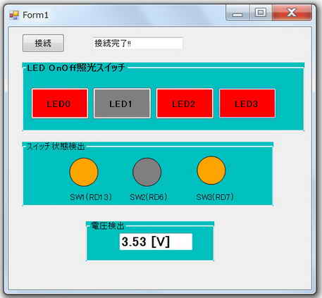
�����s���ʁ�
�@�ڑ��{�^�����N���b�N������ALED0�ALED2�ALED3��_���������Ƃ���ł��B
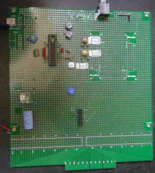
���APIC18F14K50�̃L�o����ɂ͖{ðςƊW�Ȃ����i�����X���ڂ���Ă��܂��B
���@PIC18F14K50�@HID�N���X�@�X�C�b�`�̏�ԁ��d�� �Ǎ��E�\��
�@�@
������i�d�l��
�@�EPC��PIC�Ԃ�USB�ʐM��HID�N���X�Ƃ���B
�@�EPIC18F14K50�̃L�o����̃X�C�b�`�~3�������Ɓ@PC�iWindows)��̑Ή�����ovalShape�~3�̐F���@�D�F���I�����W�F�ɕς�邱��
�@�EPC��PIC�Ԃ�USB�ʐM��HID�N���X�Ƃ���B
�@�E�ϒ�R��~3�ɂ��ݒ肳���d����PIC18F14K50�̓���AD�R���o�[�^�œǍ��A���̓d���l[V]��PC��̑Ή�����e�L�X�g�{�b�N�X�~3�ɕ\���̂��ƁB
�@�E�e�L�X�g�{�b�N�X�ɕ\�������d��[V]�́A�����_�ȉ�2���Ƃ���B
�@�EUSB�ʐMON�̃{�^���{�^���X�C�b�`���t�H�[����ɂ������邱�ƁB�@�܂�USB�ʐM���m��������h�ڑ������I�h�̕������e�L�X�g�{�b�N�X�ɕ\���̂���
�@���@PC�̃\�t�g(VC++)�́@���������Q�Ɗ肢�܂�
������i��H�}��(����H�}��PDF�t�@�C���j�@
�@�@�@�@�@�@�@�@�@�@
������i�O�ρ����L�̎ʐ^�ɂ͏�L��H�}�ɂ͂Ȃ��A�܂��{�e�[�}�ƊW�̂Ȃ����i�����X�ʂ��Ă��܂�
�@���v���O�����၄
//
//USB HID�N���X
#include "usb.h"
#include "HardwareProfile.h"
#include "usb_function_hid.h"
/** �R���t�B�M�����[�V�����@***********************/
#pragma config CPUDIV = NOCLKDIV ,USBDIV = OFF, PCLKEN = ON
#pragma config FOSC = HS, PLLEN = ON, HFOFST = OFF
#pragma config PWRTEN = ON, BOREN = OFF, MCLRE = OFF, BORV = 30
#pragma config WDTEN = OFF, LVP = OFF, FCMEN = OFF, IESO = OFF
#pragma config CP0 = OFF, XINST = OFF
/******** USB�֘A�o�b�t�@�A�ϐ���` ****/
#pragma udata usbram2
unsigned char ReceivedDataBuffer[64];
unsigned char SendBuf[64];
#pragma udata
USB_HANDLE USBOutHandle = 0;
USB_HANDLE USBInHandle = 0;
BOOL blinkStatusValid = TRUE;
/**** �O���[�o���ϐ���`�@***/
BYTE counter;
BOOL blinkStatusValid;
/*** �R�}���h�萔��` ***/
typedef enum
{
CHECK = 0x30,
POUT = 0x31,
PIN = 0x32,
AIN = 0x33,
RESET = 0xFF
}TYPE_CMD;
void BlinkUSBStatus(void);
void ProcessIO(void);
void YourHighPriorityISRCode();
void YourLowPriorityISRCode();
void USBCBSendResume(void);
//���荞�݃x�N�^��`
#pragma code REMAPPED_HIGH_INTERRUPT_VECTOR = 0x08
void Remapped_High_ISR (void)
{
_asm goto YourHighPriorityISRCode _endasm
}
#pragma code REMAPPED_LOW_INTERRUPT_VECTOR = 0x18
void Remapped_Low_ISR (void)
{
_asm goto YourLowPriorityISRCode _endasm
}
//���荞�ݏ�����
#pragma code
#pragma interrupt YourHighPriorityISRCode
void YourHighPriorityISRCode()
{
USBDeviceTasks();
}
#pragma interruptlow YourLowPriorityISRCode
void YourLowPriorityISRCode()
{
}
#pragma code
void main(void)
{
ANSEL = 0x00; // �f�W�^���ɐݒ�
ANSELH =0x07; // AN8,9,10�̂݃A�i���O
TRISA = 0xFF; // RA0-5����
TRISB = 0x7F; // RB7(TX)�ȊO���ׂē���
LATC = 0; // �o�͏�����
TRISC = 0xF0; // RC6,7�A�i���O���́ARC0-3�o��
// ADC������
ADCON0 = 0; // ��~
ADCON1 = 0; // VDD-Vss
ADCON2 = 0xBE; // �E�l��,20Tad,Fosc/64
//USB�֘A
USBDeviceInit(); // USB������
USBInHandle = 0;
USBOutHandle = 0;
blinkStatusValid = TRUE; // USB�ڈ�LED�L����
USBDeviceAttach(); // USB���荞�ݗL����
while(1)
{
//USB�ڑ����Ȃ瑗��M���s
if((USBDeviceState >= CONFIGURED_STATE)&&(USBSuspendControl!=1))
ProcessIO(); // �R�}���h���s
}
}
//���[�U�[�A�v���̓��o�͏�����
void ProcessIO(void)
{
//�f�[�^��M����
if(!HIDRxHandleBusy(USBOutHandle))
{
blinkStatusValid = FALSE;
SendBuf[0] = ReceivedDataBuffer[0];
SendBuf[1] = ReceivedDataBuffer[1];
switch(ReceivedDataBuffer[0]) // �R�}���h�R�[�h�`�F�b�N
{
//�ڑ��m�F����
case CHECK:
SendBuf[2] = 'O';
SendBuf[3] = 'K';
if(!HIDTxHandleBusy(USBInHandle))
USBInHandle = HIDTxPacket(HID_EP,(BYTE*)&SendBuf[0],64);
break;
//���̓s����ԗv���Ɖ����̏ꍇ
case PIN :
if(ReceivedDataBuffer[1] == 0x31){
if(sw1)
SendBuf[2] = 0x31;
else
SendBuf[2] = 0x30;
}
else if(ReceivedDataBuffer[1] == 0x32){
if(sw2)
SendBuf[2] = 0x31;
else
SendBuf[2] = 0x30;
}
else if(ReceivedDataBuffer[1] == 0x33){
if(sw3)
SendBuf[2] = 0x31;
else
SendBuf[2] = 0x30;
}
if(!HIDTxHandleBusy(USBInHandle))
USBInHandle = HIDTxPacket(HID_EP,(BYTE*)&SendBuf[0],64);
break;
/***** �A�i���O���͗v���Ɖ��� *****/
case AIN:
/* �`���l���I����A/D�ϊ� AN8,AN9, An10 */
ADCON0 = ((ReceivedDataBuffer[1]-0x31+8) << 2) + 0x01;
ADCON0bits.GO = 1; // A/D�ϊ��J�n
while(ADCON0bits.NOT_DONE); // �ϊ������҂�
SendBuf[2] = ADRESL; // ���M�o�b�t�@�ɃZ�b�g
SendBuf[3] = ADRESH;
if(!HIDTxHandleBusy(USBInHandle))
USBInHandle = HIDTxPacket(HID_EP,(BYTE*)&SendBuf[0],64);
break;
default:
break;
}
// ���̎�M���s
USBOutHandle = HIDRxPacket(HID_EP,(BYTE*)&ReceivedDataBuffer,64);
}
}
/******************************************************************
************** USB Callback Functions *****************************
*******************************************************************/
/******************************************************************
* Function: void USBCBSuspend(void)
******************************************************************/
void USBCBSuspend(void)
{
}
/*******************************************************************
* Function: void USBCBWakeFromSuspend(void)
*******************************************************************/
void USBCBWakeFromSuspend(void)
{
}
/********************************************************************
* Function: void USBCB_SOF_Handler(void)
*******************************************************************/
void USBCB_SOF_Handler(void)
{
}
/*******************************************************************
* Function: void USBCBErrorHandler(void)
*******************************************************************/
void USBCBErrorHandler(void)
{
}
/*******************************************************************
* Function: void USBCBCheckOtherReq(void)
*******************************************************************/
void USBCBCheckOtherReq(void)
{
USBCheckHIDRequest();
}//end
/*******************************************************************
* Function: void USBCBStdSetDscHandler(void)
*******************************************************************/
void USBCBStdSetDscHandler(void)
{
}//end
/*******************************************************************
* Function: void USBCBInitEP(void)
*******************************************************************/
void USBCBInitEP(void)
{
//enable the HID endpoint
USBEnableEndpoint(HID_EP,USB_IN_ENABLED|USB_OUT_ENABLED|USB_HANDSHAKE_ENABLED|USB_DISALLOW_SETUP);
//Re-arm the OUT endpoint for the next packet
USBOutHandle = HIDRxPacket(HID_EP,(BYTE*)&ReceivedDataBuffer,64);
}
/*******************************************************************
* Function: void USBCBSendResume(void)
******************************************************************/
void USBCBSendResume(void)
{
static WORD delay_count;
if(USBGetRemoteWakeupStatus() == TRUE)
{
//Verify that the USB bus is in fact suspended, before we send
//remote wakeup signalling.
if(USBIsBusSuspended() == TRUE)
{
USBMaskInterrupts();
//Clock switch to settings consistent with normal USB operation.
USBCBWakeFromSuspend();
USBSuspendControl = 0;
USBBusIsSuspended = FALSE; //So we don't execute this code again,
delay_count = 3600U;
do
{
delay_count--;
}while(delay_count);
//Now drive the resume K-state signalling onto the USB bus.
USBResumeControl = 1; // Start RESUME signaling
delay_count = 1800U; // Set RESUME line for 1-13 ms
do
{
delay_count--;
}while(delay_count);
USBResumeControl = 0; //Finished driving resume signalling
USBUnmaskInterrupts();
}
}
}
/*******************************************************************
* Function: BOOL USER_USB_CALLBACK_EVENT_HANDLER(
*******************************************************************/
BOOL USER_USB_CALLBACK_EVENT_HANDLER(USB_EVENT event, void *pdata, WORD size)
{
switch(event)
{
case EVENT_TRANSFER:
break;
case EVENT_SOF:
USBCB_SOF_Handler();
break;
case EVENT_SUSPEND:
USBCBSuspend();
break;
case EVENT_RESUME:
USBCBWakeFromSuspend();
break;
case EVENT_CONFIGURED:
USBCBInitEP();
break;
case EVENT_SET_DESCRIPTOR:
USBCBStdSetDscHandler();
break;
case EVENT_EP0_REQUEST:
USBCBCheckOtherReq();
break;
case EVENT_BUS_ERROR:
USBCBErrorHandler();
break;
case EVENT_TRANSFER_TERMINATED:
break;
default:
break;
}
return TRUE;
}
//----------------------------------------------------
/********************************************************************
FileName: usb_descriptors.c
Dependencies: See INCLUDES section
Processor: PIC18 or PIC24 USB Microcontrollers
Hardware: The code is natively intended to be used on the following
hardware platforms: PICDEM�EFS USB Demo Board,
PIC18F87J50 FS USB Plug-In Module, or
Explorer 16 + PIC24 USB PIM. The firmware may be
modified for use on other USB platforms by editing the
HardwareProfile.h file.
Complier: Microchip C18 (for PIC18) or C30 (for PIC24)
Company: Microchip Technology, Inc.
Software License Agreement:
The software supplied herewith by Microchip Technology Incorporated
(the �Company�E for its PIC� Microcontroller is intended and
supplied to you, the Company�s customer, for use solely and
exclusively on Microchip PIC Microcontroller products. The
software is owned by the Company and/or its supplier, and is
protected under applicable copyright laws. All rights are reserved.
Any use in violation of the foregoing restrictions may subject the
user to criminal sanctions under applicable laws, as well as to
civil liability for the breach of the terms and conditions of this
license.
THIS SOFTWARE IS PROVIDED IN AN �AS IS�ECONDITION. NO WARRANTIES,
WHETHER EXPRESS, IMPLIED OR STATUTORY, INCLUDING, BUT NOT LIMITED
TO, IMPLIED WARRANTIES OF MERCHANTABILITY AND FITNESS FOR A
PARTICULAR PURPOSE APPLY TO THIS SOFTWARE. THE COMPANY SHALL NOT,
IN ANY CIRCUMSTANCES, BE LIABLE FOR SPECIAL, INCIDENTAL OR
CONSEQUENTIAL DAMAGES, FOR ANY REASON WHATSOEVER.
*********************************************************************
-usb_descriptors.c-
-------------------------------------------------------------------
Filling in the descriptor values in the usb_descriptors.c file:
-------------------------------------------------------------------
[Device Descriptors]
The device descriptor is defined as a USB_DEVICE_DESCRIPTOR type.
This type is defined in usb_ch9.h Each entry into this structure
needs to be the correct length for the data type of the entry.
[Configuration Descriptors]
The configuration descriptor was changed in v2.x from a structure
to a BYTE array. Given that the configuration is now a byte array
each byte of multi-byte fields must be listed individually. This
means that for fields like the total size of the configuration where
the field is a 16-bit value "64,0," is the correct entry for a
configuration that is only 64 bytes long and not "64," which is one
too few bytes.
The configuration attribute must always have the _DEFAULT
definition at the minimum. Additional options can be ORed
to the _DEFAULT attribute. Available options are _SELF and _RWU.
These definitions are defined in the usb_device.h file. The
_SELF tells the USB host that this device is self-powered. The
_RWU tells the USB host that this device supports Remote Wakeup.
[Endpoint Descriptors]
Like the configuration descriptor, the endpoint descriptors were
changed in v2.x of the stack from a structure to a BYTE array. As
endpoint descriptors also has a field that are multi-byte entities,
please be sure to specify both bytes of the field. For example, for
the endpoint size an endpoint that is 64 bytes needs to have the size
defined as "64,0," instead of "64,"
Take the following example:
// Endpoint Descriptor //
0x07, //the size of this descriptor //
USB_DESCRIPTOR_ENDPOINT, //Endpoint Descriptor
_EP02_IN, //EndpointAddress
_INT, //Attributes
0x08,0x00, //size (note: 2 bytes)
0x02, //Interval
The first two parameters are self-explanatory. They specify the
length of this endpoint descriptor (7) and the descriptor type.
The next parameter identifies the endpoint, the definitions are
defined in usb_device.h and has the following naming
convention:
_EP<##>_<dir>
where ## is the endpoint number and dir is the direction of
transfer. The dir has the value of either 'OUT' or 'IN'.
The next parameter identifies the type of the endpoint. Available
options are _BULK, _INT, _ISO, and _CTRL. The _CTRL is not
typically used because the default control transfer endpoint is
not defined in the USB descriptors. When _ISO option is used,
addition options can be ORed to _ISO. Example:
_ISO|_AD|_FE
This describes the endpoint as an isochronous pipe with adaptive
and feedback attributes. See usb_device.h and the USB
specification for details. The next parameter defines the size of
the endpoint. The last parameter in the polling interval.
-------------------------------------------------------------------
Adding a USB String
-------------------------------------------------------------------
A string descriptor array should have the following format:
rom struct{byte bLength;byte bDscType;word string[size];}sdxxx={
sizeof(sdxxx),DSC_STR,<text>};
The above structure provides a means for the C compiler to
calculate the length of string descriptor sdxxx, where xxx is the
index number. The first two bytes of the descriptor are descriptor
length and type. The rest <text> are string texts which must be
in the unicode format. The unicode format is achieved by declaring
each character as a word type. The whole text string is declared
as a word array with the number of characters equals to <size>.
<size> has to be manually counted and entered into the array
declaration. Let's study this through an example:
if the string is "USB" , then the string descriptor should be:
(Using index 02)
rom struct{byte bLength;byte bDscType;word string[3];}sd002={
sizeof(sd002),DSC_STR,'U','S','B'};
A USB project may have multiple strings and the firmware supports
the management of multiple strings through a look-up table.
The look-up table is defined as:
rom const unsigned char *rom USB_SD_Ptr[]={&sd000,&sd001,&sd002};
The above declaration has 3 strings, sd000, sd001, and sd002.
Strings can be removed or added. sd000 is a specialized string
descriptor. It defines the language code, usually this is
US English (0x0409). The index of the string must match the index
position of the USB_SD_Ptr array, &sd000 must be in position
USB_SD_Ptr[0], &sd001 must be in position USB_SD_Ptr[1] and so on.
The look-up table USB_SD_Ptr is used by the get string handler
function.
-------------------------------------------------------------------
The look-up table scheme also applies to the configuration
descriptor. A USB device may have multiple configuration
descriptors, i.e. CFG01, CFG02, etc. To add a configuration
descriptor, user must implement a structure similar to CFG01.
The next step is to add the configuration descriptor name, i.e.
cfg01, cfg02,.., to the look-up table USB_CD_Ptr. USB_CD_Ptr[0]
is a dummy place holder since configuration 0 is the un-configured
state according to the definition in the USB specification.
********************************************************************/
/*********************************************************************
* Descriptor specific type definitions are defined in:
* usb_device.h
*
* Configuration options are defined in:
* usb_config.h
********************************************************************/
#ifndef __USB_DESCRIPTORS_C
#define __USB_DESCRIPTORS_C
/** INCLUDES *******************************************************/
#include "usb.h"
#include "usb_function_hid.h"
/** CONSTANTS ******************************************************/
#if defined(__18CXX)
#pragma romdata
#endif
/* Device Descriptor */
ROM USB_DEVICE_DESCRIPTOR device_dsc=
{
0x12, // Size of this descriptor in bytes
USB_DESCRIPTOR_DEVICE, // DEVICE descriptor type
0x0200, // USB Spec Release Number in BCD format
0x00, // Class Code
0x00, // Subclass code
0x00, // Protocol code
USB_EP0_BUFF_SIZE, // Max packet size for EP0, see usb_config.h
0x04D8, // Vendor ID
0x003F, // Product ID: Custom HID demo
0x0002, // Device release number in BCD format
0x01, // Manufacturer string index
0x02, // Product string index
0x00, // Device serial number string index
0x01 // Number of possible configurations
};
/* Configuration 1 Descriptor */
ROM BYTE configDescriptor1[]={
/* Configuration Descriptor */
0x09, //sizeof(USB_CFG_DSC), // Size of this descriptor in bytes
USB_DESCRIPTOR_CONFIGURATION, // CONFIGURATION descriptor type
0x29,0x00, // Total length of data for this cfg
1, // Number of interfaces in this cfg
1, // Index value of this configuration
0, // Configuration string index
_DEFAULT | _SELF, // Attributes, see usb_device.h
50, // Max power consumption (2X mA)
/* Interface Descriptor */
0x09, //sizeof(USB_INTF_DSC), // Size of this descriptor in bytes
USB_DESCRIPTOR_INTERFACE, // INTERFACE descriptor type
0, // Interface Number
0, // Alternate Setting Number
2, // Number of endpoints in this intf
HID_INTF, // Class code
0, // Subclass code
0, // Protocol code
0, // Interface string index
/* HID Class-Specific Descriptor */
0x09, //sizeof(USB_HID_DSC)+3, // Size of this descriptor in bytes
DSC_HID, // HID descriptor type
0x11,0x01, // HID Spec Release Number in BCD format (1.11)
0x00, // Country Code (0x00 for Not supported)
HID_NUM_OF_DSC, // Number of class descriptors, see usbcfg.h
DSC_RPT, // Report descriptor type
HID_RPT01_SIZE,0x00, //sizeof(hid_rpt01), // Size of the report descriptor
/* Endpoint Descriptor */
0x07, /*sizeof(USB_EP_DSC)*/
USB_DESCRIPTOR_ENDPOINT, //Endpoint Descriptor
HID_EP | _EP_IN, //EndpointAddress
_INTERRUPT, //Attributes
0x40,0x00, //size
0x01, //Interval
/* Endpoint Descriptor */
0x07, /*sizeof(USB_EP_DSC)*/
USB_DESCRIPTOR_ENDPOINT, //Endpoint Descriptor
HID_EP | _EP_OUT, //EndpointAddress
_INTERRUPT, //Attributes
0x40,0x00, //size
0x01 //Interval
};
//Language code string descriptor
ROM struct{BYTE bLength;BYTE bDscType;WORD string[1];}sd000={
sizeof(sd000),USB_DESCRIPTOR_STRING,{0x0409
}};
//Manufacturer string descriptor
ROM struct{BYTE bLength;BYTE bDscType;WORD string[25];}sd001={
sizeof(sd001),USB_DESCRIPTOR_STRING,
{'M','i','c','r','o','c','h','i','p',' ',
'T','e','c','h','n','o','l','o','g','y',' ','I','n','c','.'
}};
//Product string descriptor
ROM struct{BYTE bLength;BYTE bDscType;WORD string[22];}sd002={
sizeof(sd002),USB_DESCRIPTOR_STRING,
{'S','i','m','p','l','e',' ','H','I','D',' ',
'D','e','v','i','c','e',' ','D','e','m','o'
}};
//Class specific descriptor - HID
ROM struct{BYTE report[HID_RPT01_SIZE];}hid_rpt01={
{
0x06, 0x00, 0xFF, // Usage Page = 0xFF00 (Vendor Defined Page 1)
0x09, 0x01, // Usage (Vendor Usage 1)
0xA1, 0x01, // Collection (Application)
0x19, 0x01, // Usage Minimum
0x29, 0x40, // Usage Maximum //64 input usages total (0x01 to 0x40)
0x15, 0x01, // Logical Minimum (data bytes in the report may have minimum value = 0x00)
0x25, 0x40, // Logical Maximum (data bytes in the report may have maximum value = 0x00FF = unsigned 255)
0x75, 0x08, // Report Size: 8-bit field size
0x95, 0x40, // Report Count: Make sixty-four 8-bit fields (the next time the parser hits an "Input", "Output", or "Feature" item)
0x81, 0x00, // Input (Data, Array, Abs): Instantiates input packet fields based on the above report size, count, logical min/max, and usage.
0x19, 0x01, // Usage Minimum
0x29, 0x40, // Usage Maximum //64 output usages total (0x01 to 0x40)
0x91, 0x00, // Output (Data, Array, Abs): Instantiates output packet fields. Uses same report size and count as "Input" fields, since nothing new/different was specified to the parser since the "Input" item.
0xC0} // End Collection
};
//Array of configuration descriptors
ROM BYTE *ROM USB_CD_Ptr[]=
{
(ROM BYTE *ROM)&configDescriptor1
};
//Array of string descriptors
ROM BYTE *ROM USB_SD_Ptr[]=
{
(ROM BYTE *ROM)&sd000,
(ROM BYTE *ROM)&sd001,
(ROM BYTE *ROM)&sd002
};
/** EOF usb_descriptors.c ***************************************************/
#endif
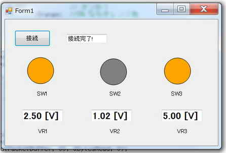
�����s���ʁ�
�@�E�ڑ��{�^�����N���b�N����USB�ڑ���������Ɂ@�X�C�b�`�{�^��SW1��SW3������������PC�̃t�H�[����ʂł��B
�@�EovalShape���I�����W�F�ɂȂ��Ă���X�C�b�`��ON��Ԃ�����킵�A�D�F��OFF��Ԃ̏ꍇ�ł��B
�@�E�e�L�X�g�{�b�N�X�ɕ\������Ă���l�́APIC18F14K50���ǂݍ��d���l�ŁA�����_�ȉ�2���ŕ\������Ă��܂��B
�@�EPIC18F14K50�̃L�o����̃X�C�b�`�~3�������Ɓ@PC�iWindows)��̑Ή�����ovalShape�~3�̐F���@�D�F���I�����W�F�ɕς�邱��
�@�EPC��PIC�Ԃ�USB�ʐM��HID�N���X�Ƃ���B
�@�E�ϒ�R��~3�ɂ��ݒ肳���d����PIC18F14K50����AD�R���o�[�^�œǍ��A���̓d���l[V]��PC��̑Ή�����e�L�X�g�{�b�N�X�~3�ɕ\���̂��ƁB
�@�E�e�L�X�g�{�b�N�X�ɕ\�������d��[V]�́A�����_�ȉ�2���Ƃ���B
�@�EUSB�ʐMON�̃{�^���{�^���X�C�b�`���t�H�[����ɂ������邱�ƁB�@�܂�USB�ʐM���m��������h�ڑ������I�h�̕������e�L�X�g�{�b�N�X�ɕ\���̂���
�@�@
���@PIC32MX795F512L�@HID�N���X�@LED�_��/�����AAD�R���o�[�^�Ǎ��E�\��
������i�d�l��
�@�@�EPC��PIC�Ԃ�USB�ʐM��HID�N���X�Ƃ���B
�@�@�EPC�iWindows)��̃{�^���X�C�b�`�~4���N���b�N����Ɓ@PIC32MX795F512L�̃L�o����̑Ή�����LED��ON/OFF���邱��
�@�@�EPC��PIC�Ԃ�USB�ʐM��HID�N���X�Ƃ���B
�@�@�E�{�^���X�C�b�`��LED��ON���Ă���Ƃ��͐ԐF�AOFF�̎��͊D�F�Ƃ���B
�@�@�EUSB�ʐMON�̃{�^���{�^���X�C�b�`���t�H�[����ɂ������邱�ƁB�@�܂�USB�ʐM���m��������h�ڑ������I�h�̕������e�L�X�g�{�b�N�X�ɕ\���̂���
�@�@�EPIC32MX795F512L�̃L�o����̃X�C�b�`�~3�������Ɓ@PC�iWindows)��̑Ή�����ovalShape�~3�̐F���@�D�F���I�����W�F�ɕς�邱��
�@�@�E�ϒ�R��ɂ��ݒ肳���d����PIC32MX795F512L����AD�R���o�[�^�œǍ��A���̓d���l[V]��PC��̃e�L�X�g�{�b�N�X�ɕ\���̂��ƁB
�@�@�E�e�L�X�g�{�b�N�X�ɕ\�������d��[V]�́A�����_�ȉ�2���Ƃ���B
�@�@�EUSB�ʐMON�̃{�^���{�^���X�C�b�`���t�H�[����ɂ������邱�ƁB�@�܂�USB�ʐM���m��������h�ڑ������I�h�̕������e�L�X�g�{�b�N�X�ɕ\���̂���
�@���@PC���̃\�t�g�iWindows)�́@���������Q�Ɗ肢�܂��@
�@�@�@
������i��H�}��(����H�}��PDF�t�@�C���j
������i�O�ρ����L�̎ʐ^�ɂ͏�L��H�}�ɂ͂Ȃ��A�܂��{�e�[�}�ƊW�̂Ȃ����i�����X�ʂ��Ă��܂�
�@���v���O�����၄
//main.c //32MX795
#include "./USB/usb.h"
#include "HardwareProfile.h"
#include "./USB/usb_function_hid.h"
//�V�X�e���N���b�N80MH�� �y���t�F�����N���b�N80MH��
#pragma config UPLLEN = ON // USB PLL Enabled
#pragma config FPLLMUL = MUL_20 // PLL Multiplier
#pragma config UPLLIDIV = DIV_2 // USB PLL Input Divider
#pragma config FPLLIDIV = DIV_2 // PLL Input Divider
#pragma config FPLLODIV = DIV_1 // PLL Output Divider
#pragma config FPBDIV = DIV_1 // Peripheral Clock divisor
#pragma config FWDTEN = OFF // Watchdog Timer
#pragma config WDTPS = PS1 // Watchdog Timer Postscale
#pragma config FCKSM = CSDCMD // Clock Switching & Fail Safe Clock Monitor
#pragma config OSCIOFNC = OFF // CLKO Enable
#pragma config POSCMOD = HS // Primary Oscillator
#pragma config IESO = OFF // Internal/External Switch-over
#pragma config FSOSCEN = OFF // Secondary Oscillator Enable (KLO was off)
#pragma config FNOSC = PRIPLL // Oscillator Selection
#pragma config CP = OFF // Code Protect
#pragma config BWP = OFF // Boot Flash Write Protect
#pragma config PWP = OFF // Program Flash Write Protect
#pragma config ICESEL = ICS_PGx2 // ICE/ICD Comm Channel Select
#define RX_DATA_BUFFER_ADDRESS
#define TX_DATA_BUFFER_ADDRESS
unsigned char ReceivedDataBuffer[64] RX_DATA_BUFFER_ADDRESS;
unsigned char ToSendDataBuffer[64] TX_DATA_BUFFER_ADDRESS;
unsigned char SendBuf[64];
USB_HANDLE USBOutHandle = 0; //USB handle. Must be initialized to 0 at startup.
USB_HANDLE USBInHandle = 0; //USB handle. Must be initialized to 0 at startup.
BOOL blinkStatusValid = TRUE;
void BlinkUSBStatus(void);
void ProcessIO(void);
void YourHighPriorityISRCode();
void YourLowPriorityISRCode();
void USBCBSendResume(void);
WORD_VAL ReadPOT(void);
unsigned int AdcValue;
int main(void)
{
SYSTEMConfigPerformance(80000000); //�V�X�e���œK��
DDPCONbits.JTAGEN = 0; //JTAG������
AD1PCFG = 0xFFFF; //�SRB�|�[�g�f�W�^���s���Ƃ��Ďg�p
AD1PCFGbits.PCFG9 = 0; //AN9�F�A�i���O
TRISBbits.TRISB9 = 1;
TRISAbits.TRISA2 = 0;
TRISAbits.TRISA3 = 0;
TRISAbits.TRISA4 = 0;
TRISAbits.TRISA5 = 0;
LATAbits.LATA2 = 0;
LATAbits.LATA3 = 0;
LATAbits.LATA4 = 0;
LATAbits.LATA5 = 0;
TRISDbits.TRISD6=1;
TRISDbits.TRISD7=1;
TRISDbits.TRISD13=1;
//AD1CON1���W�X�^�̐ݒ�
AD1CON1bits.ON = 1; //A/D�R���o�[�^���W���[���L��
// AD1CON1bits.FRZ = 0; //�f�o�b�O���[�h�ɉ����Ă�����p��
AD1CON1bits.SIDL = 0; //�A�C�h�����[�h�������W���[������p��
AD1CON1bits.FORM2 = 0; //AD1CON1bits.FORM2-AD1CON1bits.FORM0�̃Z�b�g�ŏo�̓f�[�^�`���w��@���@000�F16�r�b�g�����Ȃ������`��
AD1CON1bits.FORM1 = 0; //011:�����t�Œ�16�r�b�g�����@010�F�Œ菬��16�r�b�g�@001�F�����t������16�r�b�g�@000�F16�r�b�g�����Ȃ�����
AD1CON1bits.FORM0 = 0; //111�F�����t32�r�b�g�Œ菬���@110�F32�r�b�g�Œ菬���@101�F�����t32�r�b�g�����@100��32�r�b�g�����Ȃ�����
//���@Michrochip �f�[�^�V�[�gDS61104 �ł�000�A100��Integer�ƂȂ��Ă��邪Unsigned Integer�̌�A�ł���B�@
AD1CON1bits.SSRC2 = 1; //AD1CON1bits.SSRC2-AD1CON1bits.SSRC0 �̃Z�b�g�Ńg���K�[�\�[�X���w��
AD1CON1bits.SSRC1 = 1; //111�F�@�����J�E���^�ŃT���v�����O���I�������ϊ����J�n����
AD1CON1bits.SSRC0 = 1; //�i�Q�l�j000�F�@SAMP�r�b�g�ŃT���v�����O���I�����ϊ����J�n����
AD1CON1bits.CLRASAM = 0;//AD�ϊ����荞�ݎ��̕ϊ���~�@0�F���̕ϊ��l�ŃI�[�o�[���C�g
AD1CON1bits.ASAM = 0; //SAMP�r�b�g�̃Z�b�g�ŃT���v�����O���J�n����B�i�Q�l�j1�F�@�����J�n�i�O�̕ϊ��I���シ���T���v�����O���J�n����j
AD1CON1bits.SAMP = 0; //�T���v�����O��~
//AD1CON2���W�X�^�̐ݒ�
AD1CON2bits.VCFG2 = 0; //���t�@�����X�I��//AD1CON2bits.VCFG2 - AD1CON2bits.VCFG0�iVCFG��2�F0���j��3�r�b�g�ŃZ�b�g
AD1CON2bits.VCFG1 = 0; //��000�F���t�@�����X�d���@���@Vdd�@-Vss
AD1CON2bits.VCFG0 = 0; //�i�Q�l�j001�F���t�@�����X�d�� �� �O������ -�@Vss ��
AD1CON2bits.OFFCAL = 0; //�r�����[�h�ݒ�@0�F�T���v���z�[���h����SHA�̓��͂�AD1CHS���W�X�^��AD1CSSL���W�X�^�Ő��䂳���
AD1CON2bits.CSCNA = 1; //���}���`�v���N�TMUXA�ł̃X�L�����F�@����
AD1CON2bits.SMPI3 = 0; //���荞�݃^�C�~���O�@AD1CON2bits.SMPI3 - AD1CON2bits.SMPI0�iSMPI<3:0>�j��4�r�b�g�ŃZ�b�g
AD1CON2bits.SMPI2 = 0; //0000�F�@AD�ϊ��������̊��荞�ݔ����i���荞�ݗL���̏ꍇ�j
AD1CON2bits.SMPI1 = 0; //(�Q�l�j0011�F�@4�T���v����AD�ϊ��I���� ���荞�ݔ����i���荞�ݗL���̏ꍇ�j
AD1CON2bits.SMPI0 = 0; //
AD1CON2bits.BUFM = 0; //�o�b�t�@�[��1��16���[�h�o�b�t�@�Ƃ���B�@�i�Q�l�j1�F�@2�g��8���[�h�o�b�t�@�[�Ƃ���
AD1CON2bits.ALTS = 0; //���MUXA����̓}���`�v���N�T�ɂ���@�i�Q�l�j1�F�@MUXA,MUXB�����݂ɂ���
//AD1CON3���W�X�^�̐ݒ�
AD1CON3bits.ADRC = 0; //AD�ϊ��N���b�N���I��//0�F�@PBCLK�iPeripheral Bus Clock)�@�i�Q�l�j1�F�@A/D����RC�N���b�N
AD1CON3bits.SAMC4 = 1; //AD1CON3bits.SAMC4 - AD1CON3bits.SAMC0(SAMC<4:0>)��5�r�b�g�ŃZ�b�g
AD1CON3bits.SAMC3 = 1; //�A�N�C�W�V�����^�C���iTad�i�N���b�N�����j�~N�j�ݒ�i�z�[���h�L���p�V�^�[�d���v���ԁj
AD1CON3bits.SAMC2 = 1; //1111�F 31Tad
AD1CON3bits.SAMC1 = 1; //�i�Q�l�j0001�F 1Tad �@0010�F 2Tad �@�@�@0011�F 3Tad�@�@�E�E�E�E
AD1CON3bits.SAMC0 = 1; //
AD1CON3bits.ADCS7 = 0; //AD�ϊ����Ԃ̐ݒ�/AD1CON3bits.ADCS7 -�@AD1CON3bits.ADCS0�iADCS��7�F0���j��8�r�b�g�ŃZ�b�g
//AD�ϊ������t���OAD1CON1bits.DONE�ɂ��AAD�ϊ����������m����ꍇ�͐ݒ�s�v
AD1CON3bits.ADCS6 = 0; //AD�ϊ������܂ł̂̃N���b�N���I���r�b�g
AD1CON3bits.ADCS5 = 0; //0000 0101�F�@1Tad = 6Tpb �iTpb�F�@PBCLK�̎����j
AD1CON3bits.ADCS4 = 0; //�i�Q�l�j 0000 0000�F�@1Tad�@=�@2Tpb
AD1CON3bits.ADCS3 = 0; // 0000 0001�F�@1Tad = 3Tpb
AD1CON3bits.ADCS2 = 1; // 0000 0010�F�@1Tad�@=�@4Tpb
AD1CON3bits.ADCS1 = 0; // �@�@�E�E�E�E�@�@�@�@
AD1CON3bits.ADCS0 = 1; //�@�@�@�@�@1111 1111�F 1Tad = 512Tpb
//AD1CHS���W�X�^�̐ݒ�@//SHA�́{�[�q�Ɓ[�[�q�ւ̐ڑ��i�|�[�g�j�ݒ�
//�}���`�v���N�T�FMUXB��
AD1CHSbits.CH0NB = 0; //�������͑I���r�b�g�F�@0�FVR- �A1�FAN1
AD1CHSbits.CH0SB3 = 0; //�������͑I���r�b�g//0000�FAN0, 0001:AN1, 0011:AN2�@�D�D�D�D�@�@1111�F�@AN15
AD1CHSbits.CH0SB2 = 0; //��MUXA�������g���̂ŁACH0SB0-CH0SB3�͏o�͂ɖ��W
AD1CHSbits.CH0SB1 = 0; //
AD1CHSbits.CH0SB0 = 0; //
//�}���`�v���N�T�FMUXA��
AD1CHSbits.CH0NA = 0; //�������͑I���r�b�g�F�@0�FVR- �A1�FAN1
// AD1CHSbits.CH0SA3 = 0; //�������͑I���r�b�g//0000�FAN0, 0001:AN1, 0010:AN2�@�D�D�D�D�@�@1111�F�@AN15
// AD1CHSbits.CH0SA2 = 1; //0100�}���`�v���N�TMUXA�̐������́F�@AN4
// AD1CHSbits.CH0SA1 = 0; //
// AD1CHSbits.CH0SA0 = 0; //
AD1CHSbits.CH0SA = 9; //AN9
//AD1PCFG���W�X�^�̐ݒ�@//�A�i���O����or�f�W�^�����͑I���@//1�F�f�W�^���A�@0�F�A�i���O
//�@���f�o�C�X���Z�b�g�ł͑S�r�b�g0�ƂȂ邽�߃f�t�H���g�ł̓A�i���O���͂ƂȂ�̂Ńf�W�^���Ŏg�����d�s���́A�R���t�B�O���[�V�����Ńf�W�^���ݒ肪�K�v!!�@
AD1PCFGbits.PCFG15 = 1;//RB15/AN15
AD1PCFGbits.PCFG14 = 1;//RB14/AN14
AD1PCFGbits.PCFG13 = 1;//RB13/AN13
AD1PCFGbits.PCFG12 = 1;//RB12/AN12
AD1PCFGbits.PCFG11 = 1;//RB11/AN11
AD1PCFGbits.PCFG10 = 1;//RB10/AN10
AD1PCFGbits.PCFG9 = 0;//RB9/AN9 //�A�i���O
AD1PCFGbits.PCFG8 = 1;//RB8/AN8
AD1PCFGbits.PCFG7 = 1;//RB7/AN7
AD1PCFGbits.PCFG6 = 1;//RB6/AN6
AD1PCFGbits.PCFG5 = 1;//RB5/AN5
AD1PCFGbits.PCFG4 = 1;//RB4/AN4
AD1PCFGbits.PCFG3 = 1;//RB3/AN3
AD1PCFGbits.PCFG2 = 1;//RB2/AN2
AD1PCFGbits.PCFG1 = 1;//RB1/AN1
AD1PCFGbits.PCFG0 = 1;//RB0/AN0
// AD1CSSL���W�X�^�̐ݒ�
//�ǂݍ��ރ`�����l���i���͒[�q�j���Z�b�g����//0:�X�L�������Ȃ��@1�F�X�L��������
AD1CSSLbits.CSSL15 = 0; //AN15
AD1CSSLbits.CSSL14 = 0; //AN14
AD1CSSLbits.CSSL13 = 0; //AN13
AD1CSSLbits.CSSL12 = 0; //AN12
AD1CSSLbits.CSSL11 = 0; //AN11
AD1CSSLbits.CSSL10 = 0; //AN10
AD1CSSLbits.CSSL9 = 1; //AN9 //�X�L��������
AD1CSSLbits.CSSL8 = 0; //AN8
AD1CSSLbits.CSSL7 = 0; //AN7
AD1CSSLbits.CSSL6 = 0; //AN6
AD1CSSLbits.CSSL5 = 0; //AN5
AD1CSSLbits.CSSL4 = 0; //AN4
AD1CSSLbits.CSSL3 = 0; //AN3
AD1CSSLbits.CSSL2 = 0; //AN2
AD1CSSLbits.CSSL0 = 0; //AN0�@�@
//USB�W
USBDeviceInit();
USBOutHandle = 0;
USBInHandle = 0;
blinkStatusValid = TRUE;
USBDeviceAttach();
while(1)
{
// USB�ڑ����Ȃ瑗��M���s
if((USBDeviceState >= CONFIGURED_STATE)&&(USBSuspendControl!=1))ProcessIO();
}
}
void ProcessIO(void)
{
if(!HIDRxHandleBusy(USBOutHandle))
{
switch(ReceivedDataBuffer[0]) //�R�}���h�̎�ޔ���
{
//�ڑ��m�F����
case 0x30: //
SendBuf[2] = 'O';
SendBuf[3] = 'K';
if(!HIDTxHandleBusy(USBInHandle))
USBInHandle = HIDTxPacket(HID_EP,(BYTE*)&SendBuf[0],64); //PC���ɑ��M
break;
case 0x80: //LED�@�_��/��������
switch(ReceivedDataBuffer[1])
{
case 0x30: //RA2
if(ReceivedDataBuffer[2] == 0x30)
{
LATAbits.LATA2 = 0; //����
SendBuf[2] = 0x30;
}
else
{
LATAbits.LATA2 = 1; //�_��
SendBuf[2] = 0x31;
}
if(!HIDTxHandleBusy(USBInHandle))
USBInHandle = HIDTxPacket(HID_EP,(BYTE*)&SendBuf[0],64); //PC���ɑ��M
break;
case 0x31: //RA3
if(ReceivedDataBuffer[2] == 0x30)
{
LATAbits.LATA3 = 0;
SendBuf[3] = 0x30;
}
else
{
LATAbits.LATA3 = 1;
SendBuf[3] = 0x31;
}
if(!HIDTxHandleBusy(USBInHandle))
USBInHandle = HIDTxPacket(HID_EP,(BYTE*)&SendBuf[0],64); //PC���ɑ��M
break;
case 0x32: //RA4
if(ReceivedDataBuffer[2] == 0x30)
{
LATAbits.LATA4 = 0;
SendBuf[4] = 0x30;
}
else
{
LATAbits.LATA4 = 1;
SendBuf[4] = 0x31;
}
if(!HIDTxHandleBusy(USBInHandle))
USBInHandle = HIDTxPacket(HID_EP,(BYTE*)&SendBuf[0],64); //PC���ɑ��M
break;
case 0x33: //RA5
if(ReceivedDataBuffer[2] == 0x30)
{
LATAbits.LATA5 = 0;
SendBuf[5] = 0x30;
}
else
{
LATAbits.LATA5 = 1;
SendBuf[5] = 0x31;
}
if(!HIDTxHandleBusy(USBInHandle))
USBInHandle = HIDTxPacket(HID_EP,(BYTE*)&SendBuf[0],64); //PC���ɑ��M
break;
default :
break;
}
case 0x81: //�X�C�b�`�̏�Ԍ��o
if(ReceivedDataBuffer[1] == 0x31){
if(PORTDbits.RD13 == 0)
SendBuf[2] = 0x30;
else
SendBuf[2] = 0x31;
}
else if(ReceivedDataBuffer[1] == 0x32){
if(PORTDbits.RD6 == 0)
SendBuf[2] = 0x30;
else
SendBuf[2] = 0x31;
}
else if(ReceivedDataBuffer[1] == 0x33){
if(PORTDbits.RD7 == 0)
SendBuf[2] = 0x30;
else
SendBuf[2] = 0x31;
}
if(!HIDTxHandleBusy(USBInHandle))
USBInHandle = HIDTxPacket(HID_EP,(BYTE*)&SendBuf[0],64); //PC���ɑ��M
break;
case 0x82: //VR�d�����o
AD1CON1bits.SAMP =1; //�T���v�����O�J�n
while(!AD1CON1bits.DONE); //AD�ϊ��I���t���O�����i�P�ɂȂ�܂Łj�҂�
AdcValue = ADC1BUF0; //ADC1�̃o�b�t�@�[����AD�ϊ����ʂ�Ǎ���//��ADC1BUF1�ł͂Ȃ�
ToSendDataBuffer[2] = AdcValue; //����8�r�b�g�@at 10�r�b�g
ToSendDataBuffer[3] = AdcValue >> 8; //���2�r�b�g�@at 10�r�b�g
USBInHandle = HIDTxPacket(HID_EP,(BYTE*)&ToSendDataBuffer[0],64); //PC���ɑ��M
break;
}
//���̎�M���s
USBOutHandle = HIDRxPacket(HID_EP, (BYTE*)&ReceivedDataBuffer, 64);
}
}
// ******************************************************************************************************
// ************** USB Callback Functions ****************************************************************
// ******************************************************************************************************
void USBCBSuspend(void)
{
}
void USBCBWakeFromSuspend(void)
{
}
void USBCB_SOF_Handler(void)
{
}
void USBCBErrorHandler(void)
{
}
void USBCBCheckOtherReq(void)
{
USBCheckHIDRequest();
}
void USBCBStdSetDscHandler(void)
{
}
void USBCBInitEP(void)
{
//enable the HID endpoint
USBEnableEndpoint(HID_EP,USB_IN_ENABLED|USB_OUT_ENABLED|USB_HANDSHAKE_ENABLED|USB_DISALLOW_SETUP);
//Re-arm the OUT endpoint for the next packet
USBOutHandle = HIDRxPacket(HID_EP,(BYTE*)&ReceivedDataBuffer,64);
}
void USBCBSendResume(void)
{
static WORD delay_count;
if(USBGetRemoteWakeupStatus() == TRUE)
{
if(USBIsBusSuspended() == TRUE)
{
USBMaskInterrupts();
//Clock switch to settings consistent with normal USB operation.
USBCBWakeFromSuspend();
USBSuspendControl = 0;
USBBusIsSuspended = FALSE; //So we don't execute this code again,
//until a new suspend condition is detected.
delay_count = 3600U;
do
{
delay_count--;
}while(delay_count);
//Now drive the resume K-state signalling onto the USB bus.
USBResumeControl = 1; // Start RESUME signaling
delay_count = 1800U; // Set RESUME line for 1-13 ms
do
{
delay_count--;
}while(delay_count);
USBResumeControl = 0; //Finished driving resume signalling
USBUnmaskInterrupts();
}
}
}
BOOL USER_USB_CALLBACK_EVENT_HANDLER(int event, void *pdata, WORD size)
{
switch(event)
{
case EVENT_TRANSFER:
//Add application specific callback task or callback function here if desired.
break;
case EVENT_SOF:
USBCB_SOF_Handler();
break;
case EVENT_SUSPEND:
USBCBSuspend();
break;
case EVENT_RESUME:
USBCBWakeFromSuspend();
break;
case EVENT_CONFIGURED:
USBCBInitEP();
break;
case EVENT_SET_DESCRIPTOR:
USBCBStdSetDscHandler();
break;
case EVENT_EP0_REQUEST:
USBCBCheckOtherReq();
break;
case EVENT_BUS_ERROR:
USBCBErrorHandler();
break;
case EVENT_TRANSFER_TERMINATED:
break;
default:
break;
}
return TRUE;
}
//--------------------------------------------------------------------
/********************************************************************
FileName: usb_descriptors.c
Dependencies: See INCLUDES section
Processor: PIC18 or PIC24 USB Microcontrollers
Hardware: The code is natively intended to be used on the following
hardware platforms: PICDEM?FS USB Demo Board,
PIC18F87J50 FS USB Plug-In Module, or
Explorer 16 + PIC24 USB PIM. The firmware may be
modified for use on other USB platforms by editing the
HardwareProfile.h file.
Complier: Microchip C18 (for PIC18) or C30 (for PIC24)
Company: Microchip Technology, Inc.
Software License Agreement:
The software supplied herewith by Microchip Technology Incorporated
(the �Company? for its PIC� Microcontroller is intended and
supplied to you, the Company�s customer, for use solely and
exclusively on Microchip PIC Microcontroller products. The
software is owned by the Company and/or its supplier, and is
protected under applicable copyright laws. All rights are reserved.
Any use in violation of the foregoing restrictions may subject the
user to criminal sanctions under applicable laws, as well as to
civil liability for the breach of the terms and conditions of this
license.
THIS SOFTWARE IS PROVIDED IN AN �AS IS?CONDITION. NO WARRANTIES,
WHETHER EXPRESS, IMPLIED OR STATUTORY, INCLUDING, BUT NOT LIMITED
TO, IMPLIED WARRANTIES OF MERCHANTABILITY AND FITNESS FOR A
PARTICULAR PURPOSE APPLY TO THIS SOFTWARE. THE COMPANY SHALL NOT,
IN ANY CIRCUMSTANCES, BE LIABLE FOR SPECIAL, INCIDENTAL OR
CONSEQUENTIAL DAMAGES, FOR ANY REASON WHATSOEVER.
*********************************************************************
-usb_descriptors.c-
-------------------------------------------------------------------
Filling in the descriptor values in the usb_descriptors.c file:
-------------------------------------------------------------------
[Device Descriptors]
The device descriptor is defined as a USB_DEVICE_DESCRIPTOR type.
This type is defined in usb_ch9.h Each entry into this structure
needs to be the correct length for the data type of the entry.
[Configuration Descriptors]
The configuration descriptor was changed in v2.x from a structure
to a BYTE array. Given that the configuration is now a byte array
each byte of multi-byte fields must be listed individually. This
means that for fields like the total size of the configuration where
the field is a 16-bit value "64,0," is the correct entry for a
configuration that is only 64 bytes long and not "64," which is one
too few bytes.
The configuration attribute must always have the _DEFAULT
definition at the minimum. Additional options can be ORed
to the _DEFAULT attribute. Available options are _SELF and _RWU.
These definitions are defined in the usb_device.h file. The
_SELF tells the USB host that this device is self-powered. The
_RWU tells the USB host that this device supports Remote Wakeup.
[Endpoint Descriptors]
Like the configuration descriptor, the endpoint descriptors were
changed in v2.x of the stack from a structure to a BYTE array. As
endpoint descriptors also has a field that are multi-byte entities,
please be sure to specify both bytes of the field. For example, for
the endpoint size an endpoint that is 64 bytes needs to have the size
defined as "64,0," instead of "64,"
Take the following example:
// Endpoint Descriptor //
0x07, //the size of this descriptor //
USB_DESCRIPTOR_ENDPOINT, //Endpoint Descriptor
_EP02_IN, //EndpointAddress
_INT, //Attributes
0x08,0x00, //size (note: 2 bytes)
0x02, //Interval
The first two parameters are self-explanatory. They specify the
length of this endpoint descriptor (7) and the descriptor type.
The next parameter identifies the endpoint, the definitions are
defined in usb_device.h and has the following naming
convention:
_EP<##>_<dir>
where ## is the endpoint number and dir is the direction of
transfer. The dir has the value of either 'OUT' or 'IN'.
The next parameter identifies the type of the endpoint. Available
options are _BULK, _INT, _ISO, and _CTRL. The _CTRL is not
typically used because the default control transfer endpoint is
not defined in the USB descriptors. When _ISO option is used,
addition options can be ORed to _ISO. Example:
_ISO|_AD|_FE
This describes the endpoint as an isochronous pipe with adaptive
and feedback attributes. See usb_device.h and the USB
specification for details. The next parameter defines the size of
the endpoint. The last parameter in the polling interval.
-------------------------------------------------------------------
Adding a USB String
-------------------------------------------------------------------
A string descriptor array should have the following format:
rom struct{byte bLength;byte bDscType;word string[size];}sdxxx={
sizeof(sdxxx),DSC_STR,<text>};
The above structure provides a means for the C compiler to
calculate the length of string descriptor sdxxx, where xxx is the
index number. The first two bytes of the descriptor are descriptor
length and type. The rest <text> are string texts which must be
in the unicode format. The unicode format is achieved by declaring
each character as a word type. The whole text string is declared
as a word array with the number of characters equals to <size>.
<size> has to be manually counted and entered into the array
declaration. Let's study this through an example:
if the string is "USB" , then the string descriptor should be:
(Using index 02)
rom struct{byte bLength;byte bDscType;word string[3];}sd002={
sizeof(sd002),DSC_STR,'U','S','B'};
A USB project may have multiple strings and the firmware supports
the management of multiple strings through a look-up table.
The look-up table is defined as:
rom const unsigned char *rom USB_SD_Ptr[]={&sd000,&sd001,&sd002};
The above declaration has 3 strings, sd000, sd001, and sd002.
Strings can be removed or added. sd000 is a specialized string
descriptor. It defines the language code, usually this is
US English (0x0409). The index of the string must match the index
position of the USB_SD_Ptr array, &sd000 must be in position
USB_SD_Ptr[0], &sd001 must be in position USB_SD_Ptr[1] and so on.
The look-up table USB_SD_Ptr is used by the get string handler
function.
-------------------------------------------------------------------
The look-up table scheme also applies to the configuration
descriptor. A USB device may have multiple configuration
descriptors, i.e. CFG01, CFG02, etc. To add a configuration
descriptor, user must implement a structure similar to CFG01.
The next step is to add the configuration descriptor name, i.e.
cfg01, cfg02,.., to the look-up table USB_CD_Ptr. USB_CD_Ptr[0]
is a dummy place holder since configuration 0 is the un-configured
state according to the definition in the USB specification.
********************************************************************/
/*********************************************************************
* Descriptor specific type definitions are defined in:
* usb_device.h
*
* Configuration options are defined in:
* usb_config.h
********************************************************************/
#ifndef __USB_DESCRIPTORS_C
#define __USB_DESCRIPTORS_C
/** INCLUDES *******************************************************/
#include "./USB/usb.h"
#include "./USB/usb_function_hid.h"
/** CONSTANTS ******************************************************/
#if defined(__18CXX)
#pragma romdata
#endif
/* Device Descriptor */
ROM USB_DEVICE_DESCRIPTOR device_dsc=
{
0x12, // Size of this descriptor in bytes
USB_DESCRIPTOR_DEVICE, // DEVICE descriptor type
0x0200, // USB Spec Release Number in BCD format
0x00, // Class Code
0x00, // Subclass code
0x00, // Protocol code
USB_EP0_BUFF_SIZE, // Max packet size for EP0, see usb_config.h
0x04D8, // Vendor ID
0x003F, // Product ID: Custom HID device demo
0x0002, // Device release number in BCD format
0x01, // Manufacturer string index
0x02, // Product string index
0x00, // Device serial number string index
0x01 // Number of possible configurations
};
/* Configuration 1 Descriptor */
ROM BYTE configDescriptor1[]={
/* Configuration Descriptor */
0x09,//sizeof(USB_CFG_DSC), // Size of this descriptor in bytes
USB_DESCRIPTOR_CONFIGURATION, // CONFIGURATION descriptor type
0x29,0x00, // Total length of data for this cfg
1, // Number of interfaces in this cfg
1, // Index value of this configuration
0, // Configuration string index
_DEFAULT | _SELF, // Attributes, see usb_device.h
50, // Max power consumption (2X mA)
/* Interface Descriptor */
0x09,//sizeof(USB_INTF_DSC), // Size of this descriptor in bytes
USB_DESCRIPTOR_INTERFACE, // INTERFACE descriptor type
0, // Interface Number
0, // Alternate Setting Number
2, // Number of endpoints in this intf
HID_INTF, // Class code
0, // Subclass code
0, // Protocol code
0, // Interface string index
/* HID Class-Specific Descriptor */
0x09,//sizeof(USB_HID_DSC)+3, // Size of this descriptor in bytes
DSC_HID, // HID descriptor type
0x11,0x01, // HID Spec Release Number in BCD format (1.11)
0x00, // Country Code (0x00 for Not supported)
HID_NUM_OF_DSC, // Number of class descriptors, see usbcfg.h
DSC_RPT, // Report descriptor type
HID_RPT01_SIZE,0x00,//sizeof(hid_rpt01), // Size of the report descriptor
/* Endpoint Descriptor */
0x07,/*sizeof(USB_EP_DSC)*/
USB_DESCRIPTOR_ENDPOINT, //Endpoint Descriptor
HID_EP | _EP_IN, //EndpointAddress
_INTERRUPT, //Attributes
0x40,0x00, //size
0x01, //Interval
/* Endpoint Descriptor */
0x07,/*sizeof(USB_EP_DSC)*/
USB_DESCRIPTOR_ENDPOINT, //Endpoint Descriptor
HID_EP | _EP_OUT, //EndpointAddress
_INTERRUPT, //Attributes
0x40,0x00, //size
0x01 //Interval
};
//Language code string descriptor
ROM struct{BYTE bLength;BYTE bDscType;WORD string[1];}sd000={
sizeof(sd000),USB_DESCRIPTOR_STRING,{0x0409
}};
//Manufacturer string descriptor
ROM struct{BYTE bLength;BYTE bDscType;WORD string[25];}sd001={
sizeof(sd001),USB_DESCRIPTOR_STRING,
{'M','i','c','r','o','c','h','i','p',' ',
'T','e','c','h','n','o','l','o','g','y',' ','I','n','c','.'
}};
//Product string descriptor
ROM struct{BYTE bLength;BYTE bDscType;WORD string[22];}sd002={
sizeof(sd002),USB_DESCRIPTOR_STRING,
{'S','i','m','p','l','e',' ','H','I','D',' ',
'D','e','v','i','c','e',' ','D','e','m','o'
}};
//Class specific descriptor - HID
ROM struct{BYTE report[HID_RPT01_SIZE];}hid_rpt01={
{
0x06, 0x00, 0xFF, // Usage Page = 0xFF00 (Vendor Defined Page 1)
0x09, 0x01, // Usage (Vendor Usage 1)
0xA1, 0x01, // Collection (Application)
0x19, 0x01, // Usage Minimum
0x29, 0x40, // Usage Maximum //64 input usages total (0x01 to 0x40)
0x15, 0x01, // Logical Minimum (data bytes in the report may have minimum value = 0x00)
0x25, 0x40, // Logical Maximum (data bytes in the report may have maximum value = 0x00FF = unsigned 255)
0x75, 0x08, // Report Size: 8-bit field size
0x95, 0x40, // Report Count: Make sixty-four 8-bit fields (the next time the parser hits an "Input", "Output", or "Feature" item)
0x81, 0x00, // Input (Data, Array, Abs): Instantiates input packet fields based on the above report size, count, logical min/max, and usage.
0x19, 0x01, // Usage Minimum
0x29, 0x40, // Usage Maximum //64 output usages total (0x01 to 0x40)
0x91, 0x00, // Output (Data, Array, Abs): Instantiates output packet fields. Uses same report size and count as "Input" fields, since nothing new/different was specified to the parser since the "Input" item.
0xC0} // End Collection
};
//Array of configuration descriptors
ROM BYTE *ROM USB_CD_Ptr[]=
{
(ROM BYTE *ROM)&configDescriptor1
};
//Array of string descriptors
ROM BYTE *ROM USB_SD_Ptr[]=
{
(ROM BYTE *ROM)&sd000,
(ROM BYTE *ROM)&sd001,
(ROM BYTE *ROM)&sd002
};
/** EOF usb_descriptors.c ***************************************************/
#endif
�@
�����s���ʁ�
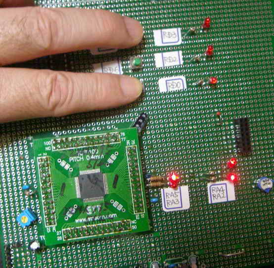
�@PC��ʂ�LED0,LED2�ALED3�{�^�����N���b�N���ā@�L�o�����LED��_�����������ƁA�L�o�����SW1��SW3������������PC�̃X�N���[���V���b�g�摜�Ʒ��݂̎ʐ^�ł��B
AD�R���o�[�^�Ō��o���ꂽ�d�����@�_�C�A���O�̃e�L�X�g�{�b�N�X�ɏ����_�ȉ�2����3.53[V}�ƕ\������Ă��܂��B
�p�\�R����ʂ�
�@�@�_�C�A���O
|
 |
PIC32MX795F512L�@�L�o�����
�@�@SW1�@��SW3���������Ƃ���
|
 |
���@PIC32MX795F512L �@HID�N���X�@�������܂ޕ�����̑���M(�L�����N�^�t���j
PIC32MX795F512L�ɃL�����N�^�t����ڑ������@USB�ʐM ����M�̗���Љ�܂��B�@�@�@���@PC���@VC++�@�\�t�g
������i�d�l��
�@�EPC������f�[�^��PIC����USB HID�N���X�ʐM�ő��M����B
�@�E���M�����R�[�h�̓V�t�gJIS���g�p����
�@�EPIC���ł͎�M������������t����i�ɁA��M�f�[�^�Ɋ�Â��ԐM�����f�[�^���t�����i�ɕ\������B
�@�EPC���ł���M�����f�[�^�����X�g�{�b�N�X�ɕ\������B
�@�EPC������̑��M�f�[�^�@�y��PIC������̕ԐM�f�[�^�͈ȉ��Ƃ���B
�@�@�@�@�@�@�@U.K. �@�@�@�@�@�@���@�@London
�@�@�@�@�@�A�@America�@�@�@�@���@�@Washington
�@�@�@�@�@�B�@Japan�@�@ �@�@�@���@�@0x938c�i���j0x8b9e�i���j
�@�@�@�@�@�C�@��(0x9286)�� (0x8D91)�@�@�@���@�k(0x966B)��(0x8B9E)
�@�@�@�@�@�D�@I am a boy.�@ �@���@�@Pardon ?
������i��H�}��(����H�}��PDF�t�@�C���j
������i�O�ρ����L�̎ʐ^�ɂ͏�L��H�}�ɂ͂Ȃ��A�܂��{�e�[�}�ƊW�̂Ȃ����i�����X�ʂ��Ă��܂�
�@���v���O�����၄
//main.c //32MX795
#include "./USB/usb.h"
#include "HardwareProfile.h"
#include "./USB/usb_function_hid.h"
#include "1lcd_lib_C32.h"
//�V�X�e���N���b�N80MH�� �y���t�F�����N���b�N60MH��
#pragma config UPLLEN = ON // USB PLL Enabled
#pragma config FPLLMUL = MUL_15 // PLL Multiplier
#pragma config UPLLIDIV = DIV_2 // USB PLL Input Divider
#pragma config FPLLIDIV = DIV_2 // PLL Input Divider
#pragma config FPLLODIV = DIV_1 // PLL Output Divider
#pragma config FPBDIV = DIV_1 // Peripheral Clock divisor
#pragma config FWDTEN = OFF // Watchdog Timer
#pragma config WDTPS = PS1 // Watchdog Timer Postscale
#pragma config FCKSM = CSDCMD // Clock Switching & Fail Safe Clock Monitor
#pragma config OSCIOFNC = OFF // CLKO Enable
#pragma config POSCMOD = HS // Primary Oscillator
#pragma config IESO = OFF // Internal/External Switch-over
#pragma config FSOSCEN = OFF // Secondary Oscillator Enable (KLO was off)
#pragma config FNOSC = PRIPLL // Oscillator Selection
#pragma config CP = OFF // Code Protect
#pragma config BWP = OFF // Boot Flash Write Protect
#pragma config PWP = OFF // Program Flash Write Protect
#pragma config ICESEL = ICS_PGx2 // ICE/ICD Comm Channel Select
#define RX_DATA_BUFFER_ADDRESS
#define TX_DATA_BUFFER_ADDRESS
unsigned char ReceivedDataBuffer[64] RX_DATA_BUFFER_ADDRESS;
unsigned char ToSendDataBuffer[64] TX_DATA_BUFFER_ADDRESS;
unsigned char SendBuf[64];
unsigned char myChr[17]; //������
char Buf[64]; //������̃o�b�t�@�[�p���W�X�^
unsigned char* str1;
char* str2;
unsigned char Japan[] = "Japan ";
unsigned char UK[] = "U.K. ";
unsigned char America[] = "America ";
//unsigned char Chuugoku[] = "Chuugoku ";
unsigned char Chuugoku[] = {0x92,0x86,0x8D,0x91,' ',' ',' ',' ',' ',' ',' ',' ',' ',' ',' ',' '};
//��[0x9286] ��[0x8D91]
//char Tokyo[] = "Tokyo \r";
char Tokyo[] = {0x93,0x8C,0x8B,0x9E,' ',' ',' ',' ',' ',' ',' ',' ',' ',' ',' ',' ','\r'};
//�V�t�gJIS�@��[938C]�A��[8B9E]
char Pekin[] = {0x96,0x6B,0x8B,0x9E,' ',' ',' ',' ',' ',' ',' ',' ',' ',' ',' ',' ','\r'};
//�V�t�gJIS �k[966B]�A��[8B9E]
char London[] = "London \r";
char Washington[] = "Washington \r";
char Pardon[] = "Pardon ? \r";
BOOL blinkStatusValid;
USB_HANDLE USBGenericOutHandle; //���M�n���h��
USB_HANDLE USBGenericInHandle; //��M�n���h��
USB_HANDLE USBOutHandle = 0; //USB handle. Must be initialized to 0 at startup.
USB_HANDLE USBInHandle = 0; //USB handle. Must be initialized to 0 at startup.
void BlinkUSBStatus(void);
void ProcessIO(void);
void YourHighPriorityISRCode();
void YourLowPriorityISRCode();
void USBCBSendResume(void);
void delay_us(unsigned int usec) //1��sec�x����
{
int count;
count = (int)(Clock/20000000)*usec;
do //�����F�@at�@Clock=80000000
{ //delay_us(1000)��1003��sec�A�@delay_us(100)��102��sec�Adelay_us(10)��11��sec�Adelay_us(1)��1.6��sec
asm("NOP"); asm("NOP"); asm("NOP"); asm("NOP"); asm("NOP");
asm("NOP"); asm("NOP"); asm("NOP"); asm("NOP"); asm("NOP");
count--;
}while(count != 0);
}
void delay_ms(unsigned int msec) //1msec�x����
{
unsigned int i;
for(i=0; i<msec; i++)
delay_us(1000);
}
int main(void)
{
int i ;
for(i = 0; i < 65; i++)Buf[i] = ' ';
SYSTEMConfigPerformance(60000000); //�V�X�e���œK��
DDPCONbits.JTAGEN = 0; //JTAG������
AD1PCFG = 0xFFFF; //�SRB�|�[�g�f�W�^���s���Ƃ��Ďg�p
TRISDbits.TRISD6=1;
TRISDbits.TRISD7=1;
TRISBbits.TRISB15 = 0; //�L�����N�^�t���|�[�g�ݒ�
TRISBbits.TRISB14 = 0; //�L�����N�^�t���|�[�g�ݒ�
TRISBbits.TRISB13 = 0; //�L�����N�^�t���|�[�g�ݒ�
TRISBbits.TRISB12 = 0; //�L�����N�^�t���|�[�g�ݒ�
TRISAbits.TRISA9 = 0; //�L�����N�^�t���|�[�g�ݒ�
TRISAbits.TRISA10 = 0; //�L�����N�^�t���|�[�g�ݒ�
//USB�W
USBDeviceInit();
USBOutHandle = 0;
USBInHandle = 0;
blinkStatusValid = TRUE;
USBDeviceAttach();
lcd_init(); // LCD������
lcd_clear(); //�N���A
lcd_cmd(0b00001100); // �J�[�\��:OFF �u�ݸ:OFF
lcd_cmd(0x80); //1�ڂ̐擪��
str1 = &myChr[0];
sprintf(Buf,"Iruma ");//
lcd_str(str1);
lcd_str(Buf); //�t���\��
lcd_cmd(0xC0); //�Q�s�ڂ̐擪��
sprintf(Buf," World !!"); //
lcd_str(Buf); // �J�n���b�Z�[�W1�s�ڕ\��
delay_ms(3000);
while(1)
{
// USB�ڑ����Ȃ瑗��M���s
if((USBDeviceState >= CONFIGURED_STATE)&&(USBSuspendControl!=1))ProcessIO();
}
}
void ProcessIO(void)
{
int i;
if(!HIDRxHandleBusy(USBOutHandle))
{
switch(ReceivedDataBuffer[0]) //�R�}���h�̎�ޔ���
{
//�ڑ��m�F����
case 0x30: //
SendBuf[2] = 'O';
SendBuf[3] = 'K';
if(!HIDTxHandleBusy(USBInHandle))
USBInHandle = HIDTxPacket(HID_EP,(BYTE*)&SendBuf[0],64); //PC���ɑ��M
break;
case 0x80: //��M������ ���@�Ή�������ԐM
for(i = 1; i < 17; i++)myChr[i-1] = ReceivedDataBuffer[i];
str1 = &myChr[0];
// str1 = &ReceivedDataBuffer[0];
if(strcmp(str1,Japan) == 0)
{
lcd_cmd(0x80); //�P�s�ڂ�
sprintf(Buf,"%s",str1);
lcd_str(Buf); //��M�f�[�^���t���ɕ\��
lcd_cmd(0xC0); //�Q�s��
sprintf(Buf,"%x%x%x%x",Tokyo[0],Tokyo[1],Tokyo[2],Tokyo[3]);
//sprintf()�̃o�O�̂��߁i�H�j���@C18�ł͐��䕶���̑O��ff������d�l�ɂȂ��Ă��邽�߂�
//�t���ɂ́@�hff93ff8Cff8Bff9E�h�@�ƕ\�������
//�V�t�gJIS�@��[938C]�A��[8B9E]
lcd_str(Buf); //���M�f�[�^���t���ɕ\��
sprintf(Buf,"%c%c%c%c",Tokyo[0],Tokyo[1],Tokyo[2],Tokyo[3]); //���M����Ƃ���%c�ɂ��đ��M
}
else if((myChr[0] == Chuugoku[0]) && (myChr[1] == Chuugoku[1]) && (myChr[2] == Chuugoku[2]) && (myChr[3] == Chuugoku[3]) &&
(myChr[4] == Chuugoku[4]) && (myChr[5] == Chuugoku[5]) && (myChr[6] == Chuugoku[6]) && (myChr[7] == Chuugoku[7]) &&
(myChr[8] == Chuugoku[8]) && (myChr[9] == Chuugoku[9]) && (myChr[10] == Chuugoku[10]) && (myChr[11] == Chuugoku[11]) &&
(myChr[12] == Chuugoku[12]) && (myChr[13] == Chuugoku[13]) && (myChr[14] == Chuugoku[14]) && (myChr[15] == Chuugoku[15]))
// else if(strcmp(str1,Chuugoku) == 0) //NG: strcmp( )��ASCII�����݂̂ɑΉ��@���䕶���ɂ͑Ή����Ă��Ȃ�
{
lcd_cmd(0x80); //�P�s�ڂ�
sprintf(Buf,"%s",str1);
lcd_str(Buf); //��M�f�[�^���t���ɕ\��
lcd_cmd(0xC0); //�Q�s��
sprintf(Buf,"%x%x%x%x",Pekin[0],Pekin[1],Pekin[2],Pekin[3]);
//sprintf()�̃o�O�̂��߁i�H�j���@C18�ł͐��䕶���̑O��ff������d�l�ɂȂ��Ă��邽�߂�
//�t���ɂ́@�hff93ff8Cff8Bff9E�h�@�ƕ\�������
//�V�t�gJIS�@��[938C]�A��[8B9E]
lcd_str(Buf); //���M�f�[�^���t���ɕ\��
sprintf(Buf,"%c%c%c%c",Pekin[0],Pekin[1],Pekin[2],Pekin[3]); //���M����Ƃ���%c�ɂ��đ��M
}
else if(strcmp(str1,UK) == 0)
{
str2 = London;
lcd_cmd(0x80); //�P�s�ڂ�
sprintf(Buf,"%s",str1);
lcd_str(Buf); //��M�f�[�^���t���ɕ\��
lcd_cmd(0xC0); //�Q�s��
sprintf(Buf,"%s",str2);
lcd_str(Buf); //���M�f�[�^���t���ɕ\��
}
else if(strcmp(str1,America) == 0)
{
str2 = Washington;
lcd_cmd(0x80); //�P�s�ڂ�
sprintf(Buf,"%s",str1);
lcd_str(Buf); //��M�f�[�^���t���ɕ\��
lcd_cmd(0xC0); //�Q�s��
sprintf(Buf,"%s",str2);
lcd_str(Buf); //���M�f�[�^���t���ɕ\��
}
else
{
str2 = Pardon;
lcd_cmd(0x80); //�P�s�ڂ�
sprintf(Buf,"%s",str1);
lcd_str(Buf); //��M�f�[�^���t���ɕ\��
lcd_cmd(0xC0); //�Q�s��
sprintf(Buf,"%s",str2);
lcd_str(Buf); //���M�f�[�^���t���ɕ\��
}
for(i = 0; i < 18; i++)SendBuf[i] = Buf[i]; //���M�f�[�^�Z�b�g
if(!HIDTxHandleBusy(USBInHandle))
USBInHandle = HIDTxPacket(HID_EP,(BYTE*)&SendBuf[0],64); //PC���ɑ��M
break;
}
//���̎�M���s
USBOutHandle = HIDRxPacket(HID_EP, (BYTE*)&ReceivedDataBuffer, 64);
}
}
// ******************************************************************************************************
// ************** USB Callback Functions ****************************************************************
// ******************************************************************************************************
void USBCBSuspend(void)
{
}
void USBCBWakeFromSuspend(void)
{
}
void USBCB_SOF_Handler(void)
{
}
void USBCBErrorHandler(void)
{
}
void USBCBCheckOtherReq(void)
{
USBCheckHIDRequest();
}
void USBCBStdSetDscHandler(void)
{
}
void USBCBInitEP(void)
{
//enable the HID endpoint
USBEnableEndpoint(HID_EP,USB_IN_ENABLED|USB_OUT_ENABLED|USB_HANDSHAKE_ENABLED|USB_DISALLOW_SETUP);
//Re-arm the OUT endpoint for the next packet
USBOutHandle = HIDRxPacket(HID_EP,(BYTE*)&ReceivedDataBuffer,64);
}
void USBCBSendResume(void)
{
static WORD delay_count;
if(USBGetRemoteWakeupStatus() == TRUE)
{
if(USBIsBusSuspended() == TRUE)
{
USBMaskInterrupts();
//Clock switch to settings consistent with normal USB operation.
USBCBWakeFromSuspend();
USBSuspendControl = 0;
USBBusIsSuspended = FALSE; //So we don't execute this code again,
//until a new suspend condition is detected.
delay_count = 3600U;
do
{
delay_count--;
}while(delay_count);
//Now drive the resume K-state signalling onto the USB bus.
USBResumeControl = 1; // Start RESUME signaling
delay_count = 1800U; // Set RESUME line for 1-13 ms
do
{
delay_count--;
}while(delay_count);
USBResumeControl = 0; //Finished driving resume signalling
USBUnmaskInterrupts();
}
}
}
BOOL USER_USB_CALLBACK_EVENT_HANDLER(int event, void *pdata, WORD size)
{
switch(event)
{
case EVENT_TRANSFER:
//Add application specific callback task or callback function here if desired.
break;
case EVENT_SOF:
USBCB_SOF_Handler();
break;
case EVENT_SUSPEND:
USBCBSuspend();
break;
case EVENT_RESUME:
USBCBWakeFromSuspend();
break;
case EVENT_CONFIGURED:
USBCBInitEP();
break;
case EVENT_SET_DESCRIPTOR:
USBCBStdSetDscHandler();
break;
case EVENT_EP0_REQUEST:
USBCBCheckOtherReq();
break;
case EVENT_BUS_ERROR:
USBCBErrorHandler();
break;
case EVENT_TRANSFER_TERMINATED:
break;
default:
break;
}
return TRUE;
}
/********************************************************************
FileName: usb_descriptors.c
Dependencies: See INCLUDES section
Processor: PIC18 or PIC24 USB Microcontrollers
Hardware: The code is natively intended to be used on the following
hardware platforms: PICDEM?FS USB Demo Board,
PIC18F87J50 FS USB Plug-In Module, or
Explorer 16 + PIC24 USB PIM. The firmware may be
modified for use on other USB platforms by editing the
HardwareProfile.h file.
Complier: Microchip C18 (for PIC18) or C30 (for PIC24)
Company: Microchip Technology, Inc.
Software License Agreement:
The software supplied herewith by Microchip Technology Incorporated
(the �Company? for its PIC� Microcontroller is intended and
supplied to you, the Company�s customer, for use solely and
exclusively on Microchip PIC Microcontroller products. The
software is owned by the Company and/or its supplier, and is
protected under applicable copyright laws. All rights are reserved.
Any use in violation of the foregoing restrictions may subject the
user to criminal sanctions under applicable laws, as well as to
civil liability for the breach of the terms and conditions of this
license.
THIS SOFTWARE IS PROVIDED IN AN �AS IS?CONDITION. NO WARRANTIES,
WHETHER EXPRESS, IMPLIED OR STATUTORY, INCLUDING, BUT NOT LIMITED
TO, IMPLIED WARRANTIES OF MERCHANTABILITY AND FITNESS FOR A
PARTICULAR PURPOSE APPLY TO THIS SOFTWARE. THE COMPANY SHALL NOT,
IN ANY CIRCUMSTANCES, BE LIABLE FOR SPECIAL, INCIDENTAL OR
CONSEQUENTIAL DAMAGES, FOR ANY REASON WHATSOEVER.
*********************************************************************
-usb_descriptors.c-
-------------------------------------------------------------------
Filling in the descriptor values in the usb_descriptors.c file:
-------------------------------------------------------------------
[Device Descriptors]
The device descriptor is defined as a USB_DEVICE_DESCRIPTOR type.
This type is defined in usb_ch9.h Each entry into this structure
needs to be the correct length for the data type of the entry.
[Configuration Descriptors]
The configuration descriptor was changed in v2.x from a structure
to a BYTE array. Given that the configuration is now a byte array
each byte of multi-byte fields must be listed individually. This
means that for fields like the total size of the configuration where
the field is a 16-bit value "64,0," is the correct entry for a
configuration that is only 64 bytes long and not "64," which is one
too few bytes.
The configuration attribute must always have the _DEFAULT
definition at the minimum. Additional options can be ORed
to the _DEFAULT attribute. Available options are _SELF and _RWU.
These definitions are defined in the usb_device.h file. The
_SELF tells the USB host that this device is self-powered. The
_RWU tells the USB host that this device supports Remote Wakeup.
[Endpoint Descriptors]
Like the configuration descriptor, the endpoint descriptors were
changed in v2.x of the stack from a structure to a BYTE array. As
endpoint descriptors also has a field that are multi-byte entities,
please be sure to specify both bytes of the field. For example, for
the endpoint size an endpoint that is 64 bytes needs to have the size
defined as "64,0," instead of "64,"
Take the following example:
// Endpoint Descriptor //
0x07, //the size of this descriptor //
USB_DESCRIPTOR_ENDPOINT, //Endpoint Descriptor
_EP02_IN, //EndpointAddress
_INT, //Attributes
0x08,0x00, //size (note: 2 bytes)
0x02, //Interval
The first two parameters are self-explanatory. They specify the
length of this endpoint descriptor (7) and the descriptor type.
The next parameter identifies the endpoint, the definitions are
defined in usb_device.h and has the following naming
convention:
_EP<##>_<dir>
where ## is the endpoint number and dir is the direction of
transfer. The dir has the value of either 'OUT' or 'IN'.
The next parameter identifies the type of the endpoint. Available
options are _BULK, _INT, _ISO, and _CTRL. The _CTRL is not
typically used because the default control transfer endpoint is
not defined in the USB descriptors. When _ISO option is used,
addition options can be ORed to _ISO. Example:
_ISO|_AD|_FE
This describes the endpoint as an isochronous pipe with adaptive
and feedback attributes. See usb_device.h and the USB
specification for details. The next parameter defines the size of
the endpoint. The last parameter in the polling interval.
-------------------------------------------------------------------
Adding a USB String
-------------------------------------------------------------------
A string descriptor array should have the following format:
rom struct{byte bLength;byte bDscType;word string[size];}sdxxx={
sizeof(sdxxx),DSC_STR,<text>};
The above structure provides a means for the C compiler to
calculate the length of string descriptor sdxxx, where xxx is the
index number. The first two bytes of the descriptor are descriptor
length and type. The rest <text> are string texts which must be
in the unicode format. The unicode format is achieved by declaring
each character as a word type. The whole text string is declared
as a word array with the number of characters equals to <size>.
<size> has to be manually counted and entered into the array
declaration. Let's study this through an example:
if the string is "USB" , then the string descriptor should be:
(Using index 02)
rom struct{byte bLength;byte bDscType;word string[3];}sd002={
sizeof(sd002),DSC_STR,'U','S','B'};
A USB project may have multiple strings and the firmware supports
the management of multiple strings through a look-up table.
The look-up table is defined as:
rom const unsigned char *rom USB_SD_Ptr[]={&sd000,&sd001,&sd002};
The above declaration has 3 strings, sd000, sd001, and sd002.
Strings can be removed or added. sd000 is a specialized string
descriptor. It defines the language code, usually this is
US English (0x0409). The index of the string must match the index
position of the USB_SD_Ptr array, &sd000 must be in position
USB_SD_Ptr[0], &sd001 must be in position USB_SD_Ptr[1] and so on.
The look-up table USB_SD_Ptr is used by the get string handler
function.
-------------------------------------------------------------------
The look-up table scheme also applies to the configuration
descriptor. A USB device may have multiple configuration
descriptors, i.e. CFG01, CFG02, etc. To add a configuration
descriptor, user must implement a structure similar to CFG01.
The next step is to add the configuration descriptor name, i.e.
cfg01, cfg02,.., to the look-up table USB_CD_Ptr. USB_CD_Ptr[0]
is a dummy place holder since configuration 0 is the un-configured
state according to the definition in the USB specification.
********************************************************************/
/*********************************************************************
* Descriptor specific type definitions are defined in:
* usb_device.h
*
* Configuration options are defined in:
* usb_config.h
********************************************************************/
#ifndef __USB_DESCRIPTORS_C
#define __USB_DESCRIPTORS_C
/** INCLUDES *******************************************************/
#include "./USB/usb.h"
#include "./USB/usb_function_hid.h"
/** CONSTANTS ******************************************************/
#if defined(__18CXX)
#pragma romdata
#endif
/* Device Descriptor */
ROM USB_DEVICE_DESCRIPTOR device_dsc=
{
0x12, // Size of this descriptor in bytes
USB_DESCRIPTOR_DEVICE, // DEVICE descriptor type
0x0200, // USB Spec Release Number in BCD format
0x00, // Class Code
0x00, // Subclass code
0x00, // Protocol code
USB_EP0_BUFF_SIZE, // Max packet size for EP0, see usb_config.h
0x04D8, // Vendor ID
0x003F, // Product ID: Custom HID device demo
0x0002, // Device release number in BCD format
0x01, // Manufacturer string index
0x02, // Product string index
0x00, // Device serial number string index
0x01 // Number of possible configurations
};
/* Configuration 1 Descriptor */
ROM BYTE configDescriptor1[]={
/* Configuration Descriptor */
0x09,//sizeof(USB_CFG_DSC), // Size of this descriptor in bytes
USB_DESCRIPTOR_CONFIGURATION, // CONFIGURATION descriptor type
0x29,0x00, // Total length of data for this cfg
1, // Number of interfaces in this cfg
1, // Index value of this configuration
0, // Configuration string index
_DEFAULT | _SELF, // Attributes, see usb_device.h
50, // Max power consumption (2X mA)
/* Interface Descriptor */
0x09,//sizeof(USB_INTF_DSC), // Size of this descriptor in bytes
USB_DESCRIPTOR_INTERFACE, // INTERFACE descriptor type
0, // Interface Number
0, // Alternate Setting Number
2, // Number of endpoints in this intf
HID_INTF, // Class code
0, // Subclass code
0, // Protocol code
0, // Interface string index
/* HID Class-Specific Descriptor */
0x09,//sizeof(USB_HID_DSC)+3, // Size of this descriptor in bytes
DSC_HID, // HID descriptor type
0x11,0x01, // HID Spec Release Number in BCD format (1.11)
0x00, // Country Code (0x00 for Not supported)
HID_NUM_OF_DSC, // Number of class descriptors, see usbcfg.h
DSC_RPT, // Report descriptor type
HID_RPT01_SIZE,0x00,//sizeof(hid_rpt01), // Size of the report descriptor
/* Endpoint Descriptor */
0x07,/*sizeof(USB_EP_DSC)*/
USB_DESCRIPTOR_ENDPOINT, //Endpoint Descriptor
HID_EP | _EP_IN, //EndpointAddress
_INTERRUPT, //Attributes
0x40,0x00, //size
0x01, //Interval
/* Endpoint Descriptor */
0x07,/*sizeof(USB_EP_DSC)*/
USB_DESCRIPTOR_ENDPOINT, //Endpoint Descriptor
HID_EP | _EP_OUT, //EndpointAddress
_INTERRUPT, //Attributes
0x40,0x00, //size
0x01 //Interval
};
//Language code string descriptor
ROM struct{BYTE bLength;BYTE bDscType;WORD string[1];}sd000={
sizeof(sd000),USB_DESCRIPTOR_STRING,{0x0409
}};
//Manufacturer string descriptor
ROM struct{BYTE bLength;BYTE bDscType;WORD string[25];}sd001={
sizeof(sd001),USB_DESCRIPTOR_STRING,
{'M','i','c','r','o','c','h','i','p',' ',
'T','e','c','h','n','o','l','o','g','y',' ','I','n','c','.'
}};
//Product string descriptor
ROM struct{BYTE bLength;BYTE bDscType;WORD string[22];}sd002={
sizeof(sd002),USB_DESCRIPTOR_STRING,
{'S','i','m','p','l','e',' ','H','I','D',' ',
'D','e','v','i','c','e',' ','D','e','m','o'
}};
//Class specific descriptor - HID
ROM struct{BYTE report[HID_RPT01_SIZE];}hid_rpt01={
{
0x06, 0x00, 0xFF, // Usage Page = 0xFF00 (Vendor Defined Page 1)
0x09, 0x01, // Usage (Vendor Usage 1)
0xA1, 0x01, // Collection (Application)
0x19, 0x01, // Usage Minimum
0x29, 0x40, // Usage Maximum //64 input usages total (0x01 to 0x40)
0x15, 0x01, // Logical Minimum (data bytes in the report may have minimum value = 0x00)
0x25, 0x40, // Logical Maximum (data bytes in the report may have maximum value = 0x00FF = unsigned 255)
0x75, 0x08, // Report Size: 8-bit field size
0x95, 0x40, // Report Count: Make sixty-four 8-bit fields (the next time the parser hits an "Input", "Output", or "Feature" item)
0x81, 0x00, // Input (Data, Array, Abs): Instantiates input packet fields based on the above report size, count, logical min/max, and usage.
0x19, 0x01, // Usage Minimum
0x29, 0x40, // Usage Maximum //64 output usages total (0x01 to 0x40)
0x91, 0x00, // Output (Data, Array, Abs): Instantiates output packet fields. Uses same report size and count as "Input" fields, since nothing new/different was specified to the parser since the "Input" item.
0xC0} // End Collection
};
//Array of configuration descriptors
ROM BYTE *ROM USB_CD_Ptr[]=
{
(ROM BYTE *ROM)&configDescriptor1
};
//Array of string descriptors
ROM BYTE *ROM USB_SD_Ptr[]=
{
(ROM BYTE *ROM)&sd000,
(ROM BYTE *ROM)&sd001,
(ROM BYTE *ROM)&sd002
};
/** EOF usb_descriptors.c ***************************************************/
#endif
//*************************************************************************
//�C���N���[�h�t�@�C�� 1lcd_lib_C32.h
//���̃t�@�C���͌�ՓN�炳�v���ꂽCCS�R���p�C���p�t���\�����C�u�����@1lcd_lib.c�����ƂɁA
//C32�R���p�C���Ή����ŕύX�������̂ł��B
//*************************************************************************
#include <proc/p32mx795f512l.h> //PIC32MX460F512L
#define Clock 80000000 // �P�ʂ�Hz�Ŏw��
// LCD�|�[�g�ݒ�
#define lcd_port_DB7 LATBbits.LATB15 //LCD��DB7�i14�ԃs��)�ɐڑ������PIC���|�[�g�ԍ��ݒ�
#define lcd_port_DB6 LATBbits.LATB14 //LCD��DB6(13�ԃs��)�ɐڑ������PIC���|�[�g�ԍ��ݒ�
#define lcd_port_DB5 LATBbits.LATB13 //��DB5(12�ԃs��)�ɐڑ������PIC���|�[�g�ԍ��ݒ�
#define lcd_port_DB4 LATBbits.LATB12 //LCD��DB4�i11�ԃs��)�ɐڑ������PIC���|�[�g�ԍ��ݒ�
#define lcd_rs LATAbits.LATA9 //LCD��rs�i4�ԃs��)�ɐڑ������PIC���|�[�g�ԍ��ݒ�
#define lcd_stb LATAbits.LATA10 //LCD��stb�i6�ԃs��)�ɐڑ������PIC���|�[�g�ԍ��ݒ�
void lcd_out(char code, char flag);
void lcd_data(char asci);
void lcd_cmd(char cmd);
void lcd_clear(void);
void lcd_init(void);
void lcd_str(char *str);
//**************************************************************************
//�C���N���[�h�t�@�C�� 1lcd_lib_C32.c
//���̃t�@�C���͌�ՓN�炳�v���ꂽCCS�R���p�C���p�t���\�����C�u���� 1lcd_lib.c�����ƂɁA
//C32�R���p�C���Ή����ŕύX�������̂ł��B
//**************************************************************************
///////////////////////////////////////////////
// �t���\���퐧�䃉�C�u�����@for C32�R���p�C���[
// �������͈ȉ�
//�@�@�@�@lcd_init() ----- ������
// lcd_cmd(cmd) ----- �R�}���h�o��
// lcd_data(chr) ----- �P�����\���o��
// lcd_clear() ----- �S����
//�@�@�@�@lcd_str(str*) -----�@������\��
//////////////////////////////////////////////
#include "1lcd_lib_C32.h"
void lcd_delay_us(unsigned int usec) //1��sec�x����
{
int count;
count = (int)(Clock/20000000)*usec;
do
{
asm("NOP"); asm("NOP"); asm("NOP"); asm("NOP"); asm("NOP");
asm("NOP"); asm("NOP"); asm("NOP"); asm("NOP"); asm("NOP");
count--;
}while(count != 0);
}
void lcd_delay_ms(unsigned int msec) //1msec�x����
{
unsigned int i;
for(i=0; i<msec; i++)
lcd_delay_us(1000);
}
//////// �f�[�^�o�̓T�u��
void lcd_out(char code, char flag)
{
if(code & 0b10000000)lcd_port_DB7 = 1; //LCD��DB7�ւ̏o�̓Z�b�g
else lcd_port_DB7 = 0;
if(code & 0b01000000)lcd_port_DB6 = 1; //LCD��DB6�ւ̏o�̓Z�b�g
else lcd_port_DB6 = 0;
if(code & 0b00100000)lcd_port_DB5 = 1; //LCD��DB5�ւ̏o�̓Z�b�g
else lcd_port_DB5 = 0;
if(code & 0b00010000)lcd_port_DB4 = 1; //LCD��DB�S�ւ̏o�̓Z�b�g
else lcd_port_DB4 = 0;
if (flag == 0)
lcd_rs = 1; // �\���f�[�^�̏ꍇ
else
lcd_rs = 0; // �R�}���h�f�[�^�̏ꍇ
lcd_delay_us(1); //1��sec�E�F�C�g
lcd_stb = 1; // strobe(E) ON�@�iEnable�j
lcd_delay_us(1); // 1��sec �F strobe�M���̕�
lcd_stb = 0; // reset strobe
}
//////// �P�����\����
void lcd_data(char asci)
{
lcd_out(asci, 0); // ��ʂS�r�b�g�o��
lcd_out(asci<<4, 0); // ���ʂS�r�b�g�o��
lcd_delay_us(50); //50��sec�E�F�C�g
}
/////// �R�}���h�o�͊�
void lcd_cmd(char cmd)
{
lcd_out(cmd, 1); // ��ʂS�r�b�g�o��
lcd_out(cmd<<4, 1); // ���ʂS�r�b�g�o��
if((cmd & 0x03) != 0) // clear Home�̏ꍇ
lcd_delay_ms(2); // 2msec�҂�
else
lcd_delay_us(50); //50��sec�E�F�C�g
}
/////// �S������
void lcd_clear(void)
{
lcd_cmd(0x01); // �������R�}���h�o��
}
/////// ������o�͊�
void lcd_str(char* str)
{
while(*str) //������I�[�� '\0'�����o����܂�
{
lcd_data(*str); //�@�P�����\��
str++; //�|�C���^���C���N�������g
}
}
/////// ��������
void lcd_init(void)
{
lcd_delay_ms(20); //20msec�E�F�C�g
lcd_out(0x30, 1); // 8bit mode set
lcd_delay_ms(5); //5msec�E�F�C�g
lcd_out(0x30, 1); // 8bit mode set
lcd_delay_ms(1); //1msec�E�F�C�g
lcd_out(0x30, 1); // 8bit mode set
lcd_delay_ms(1); //1msec�E�F�C�g
lcd_out(0x20, 1); // 4bit mode set
lcd_delay_ms(1); //1msec�E�F�C�g
lcd_cmd(0x2E); // DL=0 4bit mode
lcd_cmd(0x08); // display off C=D=B=0
lcd_cmd(0x0D); // display on C=D=1 B=0
lcd_cmd(0x06); // entry I/D=1 S=0
lcd_cmd(0x02); // cursor home
}
�@
|
PIC32MX795F512L�̉t��
��i�F�@PC����̎�M������
���i�F�@PC�ւ̕ԐM������ |
PC��� |
USB�ڑ���
�@�@�@�@���ڑ��̏�� |
-
|
 |
�ڑ��{�^�����N���b�N����
�@�@USB�ڑ���
�@�@�@�@�m��������� |
-
|
 |
�R���{�{�b�N�X����
�hU.K.�h��I�����đ��M���A
�ԐM�����X�g�{�b�N�X��
�@�@�@�@�@��M������� |
 |
 |
���ɁA�R���{�{�b�N�X����
�hAmerica�h��I�����đ��M���A
�ԐM�����X�g�{�b�N�X��
�@�@�@�@�@��M������� |
 |
 |
���ɁA�R���{�{�b�N�X����
�hJapan�h��I�����đ��M���A
�ԐM�����X�g�{�b�N�X��
�@�@�@�@�@��M������� |
 |
 |
���ɁA�R���{�{�b�N�X����
�h�����h��I�����đ��M���A
�ԐM�����X�g�{�b�N�X��
�@�@�@�@�@��M������� |
 |
 |
�Ō�ɁA�R���{�{�b�N�X����
�hI am a boy�h��I�����đ��M���A
�ԐM�����X�g�{�b�N�X��
�@�@�@�@�@��M������� |
 |
 |
�@
���@PIC32MX795F512L �@HID�N���X�@�������܂ޕ�����̑���M(�O���t�B�b�N�t���j
PIC32MX795F512L�ɃO���t�B�b�N�t����ڑ������@USB�ʐM ����M�̗���Љ�܂��B�@�@�@���@PC���@VC++�@�\�t�g
������i�d�l��
�@�EPC������f�[�^��PIC����USB HID�N���X�ʐM�ő��M����B
�@�E���M�����R�[�h�̓V�t�gJIS���g�p����
�@�EPIC���ł͎�M������������t����i�ɁA��M�f�[�^�Ɋ�Â��ԐM�����f�[�^���t�����i�ɕ\������B
�@�EPC���ł���M�����f�[�^�����X�g�{�b�N�X�ɕ\������B
�@�EPC������̑��M�f�[�^�@�y��PIC������̕ԐM�f�[�^�͈ȉ��Ƃ���B
�@�@�@�@�@�@�@U.K. �@�@�@�@�@�@���@�@London
�@�@�@�@�@�A�@America�@�@�@�@���@�@Washington
�@�@�@�@�@�B�@Japan�@�@ �@�@�@���@�@0x938c�i���j0x8b9e�i���j
�@�@�@�@�@�C�@��(0x9286)�� (0x8D91)�@�@�@���@�k(0x966B)��(0x8B9E)
�@�@�@�@�@�D�@I am a boy.�@ �@���@�@Pardon ?
������i��H�}��(����H�}��PDF�t�@�C���j
������i�O�ρ����L�̎ʐ^�ɂ͏�L��H�}�ɂ͂Ȃ��A�܂��{�e�[�}�ƊW�̂Ȃ����i�����X�ʂ��Ă��܂�
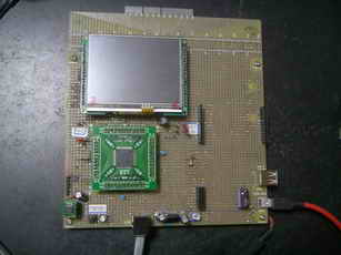
�@�@�@�@
�@�@�@�@�@�@�@�@�@�@
�@���v���O�����၄
#include "Main.h"
#include "GDD_Screens.h"
//USB�W
#include "./USB/usb.h"
#include "HardwareProfile.h"
#include "./USB/usb_function_hid.h"
#include "1lcd_lib_C32.h"
//�V�X�e���N���b�N80MH�� �y���t�F�����N���b�N60MH��
#pragma config UPLLEN = ON // USB PLL Enabled
#pragma config FPLLMUL = MUL_15 // PLL Multiplier
#pragma config UPLLIDIV = DIV_2 // USB PLL Input Divider
#pragma config FPLLIDIV = DIV_2 // PLL Input Divider
#pragma config FPLLODIV = DIV_1 // PLL Output Divider
#pragma config FPBDIV = DIV_1 // Peripheral Clock divisor
#pragma config FWDTEN = OFF // Watchdog Timer
#pragma config WDTPS = PS1 // Watchdog Timer Postscale
#pragma config FCKSM = CSDCMD // Clock Switching & Fail Safe Clock Monitor
#pragma config OSCIOFNC = OFF // CLKO Enable
#pragma config POSCMOD = HS // Primary Oscillator
#pragma config IESO = OFF // Internal/External Switch-over
#pragma config FSOSCEN = OFF // Secondary Oscillator Enable (KLO was off)
#pragma config FNOSC = PRIPLL // Oscillator Selection
#pragma config CP = OFF // Code Protect
#pragma config BWP = OFF // Boot Flash Write Protect
#pragma config PWP = OFF // Program Flash Write Protect
#pragma config ICESEL = ICS_PGx2 // ICE/ICD Comm Channel Select
// Configuration bits
// #pragma config FPLLODIV = DIV_1, FPLLMUL = MUL_20, FPLLIDIV = DIV_2, FWDTEN = OFF, FCKSM = CSECME, FPBDIV = DIV_1
// #pragma config OSCIOFNC = ON, POSCMOD = XT, FSOSCEN = ON, FNOSC = PRIPLL
// #pragma config CP = OFF, BWP = OFF, PWP = OFF
// SPI Device Initialization Function
#if defined (USE_SST25VF016)
#define FlashInit(pInitData) SST25Init((DRV_SPI_INIT_DATA*)pInitData)
#if defined (SPI_CHANNEL_2_ENABLE)
const DRV_SPI_INIT_DATA SPI_Init_Data = {SST25_SPI_CHANNEL, 1, 0, 0, 1, 1, 0};
#endif
#endif
#define RX_DATA_BUFFER_ADDRESS
#define TX_DATA_BUFFER_ADDRESS
unsigned char ReceivedDataBuffer[64] RX_DATA_BUFFER_ADDRESS;
unsigned char ToSendDataBuffer[64] TX_DATA_BUFFER_ADDRESS;
unsigned char SendBuf[64];
unsigned char myChr[17]; //������
unsigned char tempBuf[1024];
unsigned char* str10;
char Buf[64]; //������̃o�b�t�@�[�p���W�X�^
volatile DWORD tick = 0; // tick counter
unsigned char* str1;
char* str2;
unsigned char Kaigyou[] = "\n";
unsigned char Japan[] = "Japan ";
unsigned char UK[] = "U.K. ";
unsigned char America[] = "America ";
//unsigned char Chuugoku[] = "Chuugoku ";
unsigned char Chuugoku[] = {0x92,0x86,0x8D,0x91,' ',' ',' ',' ',' ',' ',' ',' ',' ',' ',' ',' '};
//��[0x9286] ��[0x8D91]
char Tokyo_english[] = "Tokyo \r";
char Tokyo[] = {0x93,0x8C,0x8B,0x9E,' ',' ',' ',' ',' ',' ',' ',' ',' ',' ',' ',' ','\r'};
//�V�t�gJIS�@��[938C]�A��[8B9E]
char Pekin[] = {0x96,0x6B,0x8B,0x9E,' ',' ',' ',' ',' ',' ',' ',' ',' ',' ',' ',' ','\r'};
//�V�t�gJIS �k[966B]�A��[8B9E]
char Pekin_english[] = "Pekin \r";
char London[] = "London \r";
char Washington[] = "Washington \r";
char Pardon[] = "Pardon ? \r";
BOOL blinkStatusValid;
USB_HANDLE USBGenericOutHandle; //���M�n���h��
USB_HANDLE USBGenericInHandle; //��M�n���h��
USB_HANDLE USBOutHandle = 0; //USB handle. Must be initialized to 0 at startup.
USB_HANDLE USBInHandle = 0; //USB handle. Must be initialized to 0 at startup.
// ���̃v���g�^�C�v�錾
void BlinkUSBStatus(void);
void ProcessIO(void);
void YourHighPriorityISRCode();
void YourLowPriorityISRCode();
void USBCBSendResume(void);
void TickInit(void); // starts tick counter
void delay_us(unsigned int usec) //1��sec�x����
{
int count;
count = (int)(Clock/20000000)*usec;
do //�����F�@at�@Clock=80000000
{ //delay_us(1000)��1003��sec�A�@delay_us(100)��102��sec�Adelay_us(10)��11��sec�Adelay_us(1)��1.6��sec
asm("NOP"); asm("NOP"); asm("NOP"); asm("NOP"); asm("NOP");
asm("NOP"); asm("NOP"); asm("NOP"); asm("NOP"); asm("NOP");
count--;
}while(count != 0);
}
void delay_ms(unsigned int msec) //1msec�x����
{
unsigned int i;
for(i=0; i<msec; i++)
delay_us(1000);
}
int main(void)
{
int i ;
for(i = 0; i < 65; i++)Buf[i] = ' ';
SYSTEMConfigPerformance(60000000); //�V�X�e���œK��
INTEnableSystemMultiVectoredInt(); //�x�N�^�������荞�݂�������
// SYSTEMConfigPerformance(GetSystemClock()); //SYSTEMConfigPerformance(80000000);// �V�X�e���œK��//�L���b�V���E�v���t�F�b�`�o�b�t�@�L����
DDPCONbits.JTAGEN = 0; //I/O�|�[�g�Ƃ���RA0�ARA1�ARA4�ARA5�������ꍇ�A�d��������DDPCON���W�X�^��bit3��0�ɁA�ݒ肷��K�v������G�܂��B
AD1PCFG =0xFFFF; //���K�{ //B�|�[�g�F�A�i���O�@���@�f�W�^��
TRISBbits.TRISB15 = 0; //�L�����N�^�t���|�[�g�ݒ�
TRISBbits.TRISB14 = 0; //�L�����N�^�t���|�[�g�ݒ�
TRISBbits.TRISB13 = 0; //�L�����N�^�t���|�[�g�ݒ�
TRISBbits.TRISB12 = 0; //�L�����N�^�t���|�[�g�ݒ�
TRISAbits.TRISA9 = 0; //�L�����N�^�t���|�[�g�ݒ�
TRISAbits.TRISA10 = 0; //�L�����N�^�t���|�[�g�ݒ�
TRISGbits.TRISG15 = 0; //RG15(1�ԃs���j�|�[�g�@LED�_���p
TRISDbits.TRISD2 = 0; //RD2 LED�_���p
TRISDbits.TRISD3 = 0; //RD3 LED�_���p
LATGbits.LATG15 = 1; //LED off
LATDbits.LATD2 = 1; //LED off
LATDbits.LATD3 = 1; //LED off
TRISBbits.TRISB0 = 1; //RB0 in port
TRISBbits.TRISB1 = 1; //RB1 in port
//USB�W
USBDeviceInit();
USBOutHandle = 0;
USBInHandle = 0;
blinkStatusValid = TRUE;
USBDeviceAttach();
lcd_init(); // LCD������
lcd_cmd(0b00001100); // �J�[�\��:OFF �u�ݸ:OFF
lcd_cmd(0x80); //1�ڂ̐擪��
sprintf(Buf,"USB HID");//
lcd_str(Buf); //�t���\��
lcd_cmd(0xC0); //�Q�s�ڂ̐擪��
sprintf(Buf," GDDX LCD Start !!"); //
lcd_str(Buf); // �J�n���b�Z�[�W1�s�ڕ\��
DisplayResetDisable(); //Sets RST high
DisplayResetConfig(); //Sets the pin to output
DelayMs(3000); //Wait 500 ms at startup
SetColor(BLACK);
ClearDevice();
GOL_MSG msg; // GOL message structure to interact with GOL
GOLInit(); // Initialize graphics library and create default style scheme for GOL
//SPI�t���b�V�������������� //Set IOs directions for SST25 SPI
//SST25VF016���Ȃ��Ɛ���ɕ\������Ȃ�
//��R����PI�̂�AD�R���o�[�^���g�p���āA�^�b�`�ʒu�����o����ꍇ�͈ʒu�Z���L���̂���SST25VF016�͕K�v
SST25_CS_LAT = 1;
SST25_CS_TRIS = 0;
SST25_SCK_TRIS = 0;
SST25_SDO_TRIS = 0;
SST25_SDI_TRIS = 1;
FlashInit(&SPI_Init_Data); // initialize the Flash Memory driver
TouchHardwareInit(); //�^�b�`�p�l��������
TickInit(); //�^�C�}4 ������
str10 = &tempBuf[0];
GDDDemoCreateFirstScreen();
while(1)
{
// USB�ڑ����Ȃ瑗��M���s
if((USBDeviceState >= CONFIGURED_STATE)&&(USBSuspendControl!=1))ProcessIO();
if(GOLDraw()) // Draw GOL object
{
TouchGetMsg(&msg); // Get message from touch screen
GOLMsg(&msg); // Process message
}
}//end while
}
/////////////////////////////////////////////////////////////////////////////
// Function: WORD GOLMsgCallback(WORD objMsg, OBJ_HEADER* pObj, GOL_MSG* pMsg)
// Input: objMsg - translated message for the object,
// pObj - pointer to the object,
// pMsg - pointer to the non-translated, raw GOL message
// Output: if the function returns non-zero the message will be processed by default
// Overview: it's a user defined function. GOLMsg() function calls it each
// time the valid message for the object received
/////////////////////////////////////////////////////////////////////////////
WORD GOLMsgCallback(WORD objMsg, OBJ_HEADER *pObj, GOL_MSG *pMsg)
{
WORD objectID;
objectID = GetObjID(pObj);
GDDDemoGOLMsgCallback(objMsg, pObj, pMsg);
// Add additional code here...
return (1);
}
/////////////////////////////////////////////////////////////////////////////
// Function: WORD GOLDrawCallback()
// Output: if the function returns non-zero the draw control will be passed to GOL
// Overview: it's a user defined function. GOLDraw() function calls it each
// time when GOL objects drawing is completed. User drawing should be done here.
// GOL will not change color, line type and clipping region settings while
// this function returns zero.
/////////////////////////////////////////////////////////////////////////////
WORD GOLDrawCallback(void)
{
GDDDemoGOLDrawCallback();
// Add additional code here...
return (1);
}
void __ISR(_TIMER_4_VECTOR, ipl1) _T4Interrupt(void) //�^�C�}4���荞�� //100msec��
{
// LATGbits.LATG15 = 0; //���荞�ݎ��ԁi�����j�F3msec
tick++;
TMR4 = 0;
mT4ClearIntFlag(); // Clear flag
TouchDetectPosition();
/*
lcd_clear(); // �S����
lcd_cmd(0x80); //1�s�ڂ̐擪��
sprintf(Buf,"X = %d",TouchGetX());//�^�b�`X���W�\��
lcd_str(Buf); //�t���\��
lcd_cmd(0xC0); //�Q�s�ڂ̐擪��
sprintf(Buf,"Y = %d",TouchGetY()); //�^�b�`Y���W�\��
lcd_str(Buf); // �J�n���b�Z�[�W1�s�ڕ\��
*/
// LATGbits.LATG15 = 1;
}
//---------------------------------------------------------------------------------
#define SAMPLE_PERIOD 500 // us
#define TICK_PERIOD (GetPeripheralClock() * SAMPLE_PERIOD) / 4000000
//TICK_PERIOD = 80000000 * 500 / 4000000 = 80* 500 / 4 = 20*500 = 10000
void TickInit(void) //�^�C�}�S������
{
OpenTimer4(T4_ON | T4_PS_1_256, 31249); //1000/80000000*256*31249�@=99.9968 msec
// OpenTimer4(T4_ON | T4_PS_1_8, 10000); //2msec
// OpenTimer4(T4_ON | T4_PS_1_8, TICK_PERIOD); //�����l�F35��sec�@//�I�[�o�[�t���[�G���[����
ConfigIntTimer4(T4_INT_ON | T4_INT_PRIOR_1);
}
void ProcessIO(void)
{
int i;
if(!HIDRxHandleBusy(USBOutHandle))
{
switch(ReceivedDataBuffer[0]) //�R�}���h�̎�ޔ���
{
//�ڑ��m�F����
case 0x30: //
SendBuf[2] = 'O';
SendBuf[3] = 'K';
if(!HIDTxHandleBusy(USBInHandle))
USBInHandle = HIDTxPacket(HID_EP,(BYTE*)&SendBuf[0],64); //PC���ɑ��M
break;
case 0x80: //��M������ ���@�Ή�������ԐM
for(i = 1; i < 17; i++)myChr[i-1] = ReceivedDataBuffer[i];
str1 = &myChr[0];
// str1 = &ReceivedDataBuffer[0];
if(strcmp(str1,Japan) == 0)
{
lcd_cmd(0x80); //�P�s�ڂ�
sprintf(Buf,"%s",str1);
lcd_str(Buf); //��M�f�[�^���t���ɕ\��
lcd_cmd(0xC0); //�Q�s��
sprintf(Buf,"%x%x%x%x",Tokyo[0],Tokyo[1],Tokyo[2],Tokyo[3]);
//sprintf()�̃o�O�̂��߁i�H�j���@C18�ł͐��䕶���̑O��ff������d�l�ɂȂ��Ă��邽�߂�
//�t���ɂ́@�hff93ff8Cff8Bff9E�h�@�ƕ\�������
//�V�t�gJIS�@��[938C]�A��[8B9E]
lcd_str(Buf); //���M�f�[�^���t���ɕ\��
sprintf(Buf,"%c%c%c%c",Tokyo[0],Tokyo[1],Tokyo[2],Tokyo[3]); //���M����Ƃ���%c�ɂ��đ��M
str2 = Tokyo_english;
}
else if((myChr[0] == Chuugoku[0]) && (myChr[1] == Chuugoku[1]) && (myChr[2] == Chuugoku[2]) && (myChr[3] == Chuugoku[3]) &&
(myChr[4] == Chuugoku[4]) && (myChr[5] == Chuugoku[5]) && (myChr[6] == Chuugoku[6]) && (myChr[7] == Chuugoku[7]) &&
(myChr[8] == Chuugoku[8]) && (myChr[9] == Chuugoku[9]) && (myChr[10] == Chuugoku[10]) && (myChr[11] == Chuugoku[11]) &&
(myChr[12] == Chuugoku[12]) && (myChr[13] == Chuugoku[13]) && (myChr[14] == Chuugoku[14]) && (myChr[15] == Chuugoku[15]))
// else if(strcmp(str1,Chuugoku) == 0) //NG: strcmp( )��ASCII�����݂̂ɑΉ��@���䕶���ɂ͑Ή����Ă��Ȃ�
{
lcd_cmd(0x80); //�P�s�ڂ�
sprintf(Buf,"%s",str1);
lcd_str(Buf); //��M�f�[�^���t���ɕ\��
lcd_cmd(0xC0); //�Q�s��
sprintf(Buf,"%x%x%x%x",Pekin[0],Pekin[1],Pekin[2],Pekin[3]);
//sprintf()�̃o�O�̂��߁i�H�j���@C18�ł͐��䕶���̑O��ff������d�l�ɂȂ��Ă��邽�߂�
//�t���ɂ́@�hff93ff8Cff8Bff9E�h�@�ƕ\�������
//�V�t�gJIS�@��[938C]�A��[8B9E]
lcd_str(Buf); //���M�f�[�^���t���ɕ\��
sprintf(Buf,"%c%c%c%c",Pekin[0],Pekin[1],Pekin[2],Pekin[3]); //���M����Ƃ���%c�ɂ��đ��M
str2 = Pekin_english;
}
else if(strcmp(str1,UK) == 0)
{
str2 = London;
lcd_cmd(0x80); //�P�s�ڂ�
sprintf(Buf,"%s",str1);
lcd_str(Buf); //��M�f�[�^���t���ɕ\��
lcd_cmd(0xC0); //�Q�s��
sprintf(Buf,"%s",str2);
lcd_str(Buf); //���M�f�[�^���t���ɕ\��
}
else if(strcmp(str1,America) == 0)
{
str2 = Washington;
lcd_cmd(0x80); //�P�s�ڂ�
sprintf(Buf,"%s",str1);
lcd_str(Buf); //��M�f�[�^���t���ɕ\��
lcd_cmd(0xC0); //�Q�s��
sprintf(Buf,"%s",str2);
lcd_str(Buf); //���M�f�[�^���t���ɕ\��
}
else
{
str2 = Pardon;
lcd_cmd(0x80); //�P�s�ڂ�
sprintf(Buf,"%s",str1);
lcd_str(Buf); //��M�f�[�^���t���ɕ\��
lcd_cmd(0xC0); //�Q�s��
sprintf(Buf,"%s",str2);
lcd_str(Buf); //���M�f�[�^���t���ɕ\��
}
//�O���t�B�b�N�t����Static Text Widget�ɕ\��
STATICTEXT *pSTE_1 = (STATICTEXT*)GOLFindObject(STE_1); //�G�f�B�b�g�{�b�N�X�̃I�u�W�F�N�g���o
pSTE_1->hdr.state = ST_DRAW; //�ĕ`��ɂ�蕶���͍��A���C���Ƀ��Z�b�g�����
strncat(str10,str2,16); //�����lj�
strncat(str10,Kaigyou,16); //���s
StSetText((STATICTEXT*)pSTE_1, str10); //
SetState(pSTE_1, ST_DRAW);
for(i = 0; i < 18; i++)SendBuf[i] = Buf[i]; //���M�f�[�^�Z�b�g
if(!HIDTxHandleBusy(USBInHandle))
USBInHandle = HIDTxPacket(HID_EP,(BYTE*)&SendBuf[0],64); //PC���ɑ��M
break;
}
//���̎�M���s
USBOutHandle = HIDRxPacket(HID_EP, (BYTE*)&ReceivedDataBuffer, 64);
}
}
// ******************************************************************************************************
// ************** USB Callback Functions ****************************************************************
// ******************************************************************************************************
void USBCBSuspend(void)
{
}
void USBCBWakeFromSuspend(void)
{
}
void USBCB_SOF_Handler(void)
{
}
void USBCBErrorHandler(void)
{
}
void USBCBCheckOtherReq(void)
{
USBCheckHIDRequest();
}
void USBCBStdSetDscHandler(void)
{
}
void USBCBInitEP(void)
{
//enable the HID endpoint
USBEnableEndpoint(HID_EP,USB_IN_ENABLED|USB_OUT_ENABLED|USB_HANDSHAKE_ENABLED|USB_DISALLOW_SETUP);
//Re-arm the OUT endpoint for the next packet
USBOutHandle = HIDRxPacket(HID_EP,(BYTE*)&ReceivedDataBuffer,64);
}
void USBCBSendResume(void)
{
static WORD delay_count;
if(USBGetRemoteWakeupStatus() == TRUE)
{
if(USBIsBusSuspended() == TRUE)
{
USBMaskInterrupts();
//Clock switch to settings consistent with normal USB operation.
USBCBWakeFromSuspend();
USBSuspendControl = 0;
USBBusIsSuspended = FALSE; //So we don't execute this code again,
//until a new suspend condition is detected.
delay_count = 3600U;
do
{
delay_count--;
}while(delay_count);
//Now drive the resume K-state signalling onto the USB bus.
USBResumeControl = 1; // Start RESUME signaling
delay_count = 1800U; // Set RESUME line for 1-13 ms
do
{
delay_count--;
}while(delay_count);
USBResumeControl = 0; //Finished driving resume signalling
USBUnmaskInterrupts();
}
}
}
BOOL USER_USB_CALLBACK_EVENT_HANDLER(int event, void *pdata, WORD size)
{
switch(event)
{
case EVENT_TRANSFER:
//Add application specific callback task or callback function here if desired.
break;
case EVENT_SOF:
USBCB_SOF_Handler();
break;
case EVENT_SUSPEND:
USBCBSuspend();
break;
case EVENT_RESUME:
USBCBWakeFromSuspend();
break;
case EVENT_CONFIGURED:
USBCBInitEP();
break;
case EVENT_SET_DESCRIPTOR:
USBCBStdSetDscHandler();
break;
case EVENT_EP0_REQUEST:
USBCBCheckOtherReq();
break;
case EVENT_BUS_ERROR:
USBCBErrorHandler();
break;
case EVENT_TRANSFER_TERMINATED:
break;
default:
break;
}
return TRUE;
}
//------------------------------------------------------------------------------
//usb_descriptors.c
/* Device Descriptor */
ROM USB_DEVICE_DESCRIPTOR device_dsc=
{
0x12, // Size of this descriptor in bytes
USB_DESCRIPTOR_DEVICE, // DEVICE descriptor type
0x0200, // USB Spec Release Number in BCD format
0x00, // Class Code
0x00, // Subclass code
0x00, // Protocol code
USB_EP0_BUFF_SIZE, // Max packet size for EP0, see usb_config.h
0x04D8, // Vendor ID
0x003F, // Product ID: Custom HID device demo
0x0002, // Device release number in BCD format
0x01, // Manufacturer string index
0x02, // Product string index
0x00, // Device serial number string index
0x01 // Number of possible configurations
};
/* Configuration 1 Descriptor */
ROM BYTE configDescriptor1[]={
/* Configuration Descriptor */
0x09,//sizeof(USB_CFG_DSC), // Size of this descriptor in bytes
USB_DESCRIPTOR_CONFIGURATION, // CONFIGURATION descriptor type
0x29,0x00, // Total length of data for this cfg
1, // Number of interfaces in this cfg
1, // Index value of this configuration
0, // Configuration string index
_DEFAULT | _SELF, // Attributes, see usb_device.h
50, // Max power consumption (2X mA)
/* Interface Descriptor */
0x09,//sizeof(USB_INTF_DSC), // Size of this descriptor in bytes
USB_DESCRIPTOR_INTERFACE, // INTERFACE descriptor type
0, // Interface Number
0, // Alternate Setting Number
2, // Number of endpoints in this intf
HID_INTF, // Class code
0, // Subclass code
0, // Protocol code
0, // Interface string index
/* HID Class-Specific Descriptor */
0x09,//sizeof(USB_HID_DSC)+3, // Size of this descriptor in bytes
DSC_HID, // HID descriptor type
0x11,0x01, // HID Spec Release Number in BCD format (1.11)
0x00, // Country Code (0x00 for Not supported)
HID_NUM_OF_DSC, // Number of class descriptors, see usbcfg.h
DSC_RPT, // Report descriptor type
HID_RPT01_SIZE,0x00,//sizeof(hid_rpt01), // Size of the report descriptor
/* Endpoint Descriptor */
0x07,/*sizeof(USB_EP_DSC)*/
USB_DESCRIPTOR_ENDPOINT, //Endpoint Descriptor
HID_EP | _EP_IN, //EndpointAddress
_INTERRUPT, //Attributes
0x40,0x00, //size
0x01, //Interval
/* Endpoint Descriptor */
0x07,/*sizeof(USB_EP_DSC)*/
USB_DESCRIPTOR_ENDPOINT, //Endpoint Descriptor
HID_EP | _EP_OUT, //EndpointAddress
_INTERRUPT, //Attributes
0x40,0x00, //size
0x01 //Interval
};
//Language code string descriptor
ROM struct{BYTE bLength;BYTE bDscType;WORD string[1];}sd000={
sizeof(sd000),USB_DESCRIPTOR_STRING,{0x0409
}};
//Manufacturer string descriptor
ROM struct{BYTE bLength;BYTE bDscType;WORD string[25];}sd001={
sizeof(sd001),USB_DESCRIPTOR_STRING,
{'M','i','c','r','o','c','h','i','p',' ',
'T','e','c','h','n','o','l','o','g','y',' ','I','n','c','.'
}};
//Product string descriptor
ROM struct{BYTE bLength;BYTE bDscType;WORD string[22];}sd002={
sizeof(sd002),USB_DESCRIPTOR_STRING,
{'S','i','m','p','l','e',' ','H','I','D',' ',
'D','e','v','i','c','e',' ','D','e','m','o'
}};
//Class specific descriptor - HID
ROM struct{BYTE report[HID_RPT01_SIZE];}hid_rpt01={
{
0x06, 0x00, 0xFF, // Usage Page = 0xFF00 (Vendor Defined Page 1)
0x09, 0x01, // Usage (Vendor Usage 1)
0xA1, 0x01, // Collection (Application)
0x19, 0x01, // Usage Minimum
0x29, 0x40, // Usage Maximum //64 input usages total (0x01 to 0x40)
0x15, 0x01, // Logical Minimum (data bytes in the report may have minimum value = 0x00)
0x25, 0x40, // Logical Maximum (data bytes in the report may have maximum value = 0x00FF = unsigned 255)
0x75, 0x08, // Report Size: 8-bit field size
0x95, 0x40, // Report Count: Make sixty-four 8-bit fields (the next time the parser hits an "Input", "Output", or "Feature" item)
0x81, 0x00, // Input (Data, Array, Abs): Instantiates input packet fields based on the above report size, count, logical min/max, and usage.
0x19, 0x01, // Usage Minimum
0x29, 0x40, // Usage Maximum //64 output usages total (0x01 to 0x40)
0x91, 0x00, // Output (Data, Array, Abs): Instantiates output packet fields. Uses same report size and count as "Input" fields, since nothing new/different was specified to the parser since the "Input" item.
0xC0} // End Collection
};
//Array of configuration descriptors
ROM BYTE *ROM USB_CD_Ptr[]=
{
(ROM BYTE *ROM)&configDescriptor1
};
//Array of string descriptors
ROM BYTE *ROM USB_SD_Ptr[]=
{
(ROM BYTE *ROM)&sd000,
(ROM BYTE *ROM)&sd001,
(ROM BYTE *ROM)&sd002
};
/** EOF usb_descriptors.c ***************************************************/
#endif
//*************************************************************************
//�C���N���[�h�t�@�C�� 1lcd_lib_C32.h
//���̃t�@�C���͌�ՓN�炳�v���ꂽCCS�R���p�C���p�t���\�����C�u�����@1lcd_lib.c�����ƂɁA
//C32�R���p�C���Ή����ŕύX�������̂ł��B
//*************************************************************************
#include <proc/p32mx795f512l.h> //PIC32MX460F512L
#define Clock 80000000 // �P�ʂ�Hz�Ŏw��
// LCD�|�[�g�ݒ�
#define lcd_port_DB7 LATBbits.LATB15 //LCD��DB7�i14�ԃs��)�ɐڑ������PIC���|�[�g�ԍ��ݒ�
#define lcd_port_DB6 LATBbits.LATB14 //LCD��DB6(13�ԃs��)�ɐڑ������PIC���|�[�g�ԍ��ݒ�
#define lcd_port_DB5 LATBbits.LATB13 //��DB5(12�ԃs��)�ɐڑ������PIC���|�[�g�ԍ��ݒ�
#define lcd_port_DB4 LATBbits.LATB12 //LCD��DB4�i11�ԃs��)�ɐڑ������PIC���|�[�g�ԍ��ݒ�
#define lcd_rs LATAbits.LATA9 //LCD��rs�i4�ԃs��)�ɐڑ������PIC���|�[�g�ԍ��ݒ�
#define lcd_stb LATAbits.LATA10 //LCD��stb�i6�ԃs��)�ɐڑ������PIC���|�[�g�ԍ��ݒ�
void lcd_out(char code, char flag);
void lcd_data(char asci);
void lcd_cmd(char cmd);
void lcd_clear(void);
void lcd_init(void);
void lcd_str(char *str);
//**************************************************************************
//�C���N���[�h�t�@�C�� 1lcd_lib_C32.c
//���̃t�@�C���͌�ՓN�炳�v���ꂽCCS�R���p�C���p�t���\�����C�u���� 1lcd_lib.c�����ƂɁA
//C32�R���p�C���Ή����ŕύX�������̂ł��B
//**************************************************************************
///////////////////////////////////////////////
// �t���\���퐧�䃉�C�u�����@for C32�R���p�C���[
// �������͈ȉ�
//�@�@�@�@lcd_init() ----- ������
// lcd_cmd(cmd) ----- �R�}���h�o��
// lcd_data(chr) ----- �P�����\���o��
// lcd_clear() ----- �S����
//�@�@�@�@lcd_str(str*) -----�@������\��
//////////////////////////////////////////////
#include "1lcd_lib_C32.h"
void lcd_delay_us(unsigned int usec) //1��sec�x����
{
int count;
count = (int)(Clock/20000000)*usec;
do
{
asm("NOP"); asm("NOP"); asm("NOP"); asm("NOP"); asm("NOP");
asm("NOP"); asm("NOP"); asm("NOP"); asm("NOP"); asm("NOP");
count--;
}while(count != 0);
}
void lcd_delay_ms(unsigned int msec) //1msec�x����
{
unsigned int i;
for(i=0; i<msec; i++)
lcd_delay_us(1000);
}
//////// �f�[�^�o�̓T�u��
void lcd_out(char code, char flag)
{
if(code & 0b10000000)lcd_port_DB7 = 1; //LCD��DB7�ւ̏o�̓Z�b�g
else lcd_port_DB7 = 0;
if(code & 0b01000000)lcd_port_DB6 = 1; //LCD��DB6�ւ̏o�̓Z�b�g
else lcd_port_DB6 = 0;
if(code & 0b00100000)lcd_port_DB5 = 1; //LCD��DB5�ւ̏o�̓Z�b�g
else lcd_port_DB5 = 0;
if(code & 0b00010000)lcd_port_DB4 = 1; //LCD��DB�S�ւ̏o�̓Z�b�g
else lcd_port_DB4 = 0;
if (flag == 0)
lcd_rs = 1; // �\���f�[�^�̏ꍇ
else
lcd_rs = 0; // �R�}���h�f�[�^�̏ꍇ
lcd_delay_us(1); //1��sec�E�F�C�g
lcd_stb = 1; // strobe(E) ON�@�iEnable�j
lcd_delay_us(1); // 1��sec �F strobe�M���̕�
lcd_stb = 0; // reset strobe
}
//////// �P�����\����
void lcd_data(char asci)
{
lcd_out(asci, 0); // ��ʂS�r�b�g�o��
lcd_out(asci<<4, 0); // ���ʂS�r�b�g�o��
lcd_delay_us(50); //50��sec�E�F�C�g
}
/////// �R�}���h�o�͊�
void lcd_cmd(char cmd)
{
lcd_out(cmd, 1); // ��ʂS�r�b�g�o��
lcd_out(cmd<<4, 1); // ���ʂS�r�b�g�o��
if((cmd & 0x03) != 0) // clear Home�̏ꍇ
lcd_delay_ms(2); // 2msec�҂�
else
lcd_delay_us(50); //50��sec�E�F�C�g
}
/////// �S������
void lcd_clear(void)
{
lcd_cmd(0x01); // �������R�}���h�o��
}
/////// ������o�͊�
void lcd_str(char* str)
{
while(*str) //������I�[�� '\0'�����o����܂�
{
lcd_data(*str); //�@�P�����\��
str++; //�|�C���^���C���N�������g
}
}
/////// ��������
void lcd_init(void)
{
lcd_delay_ms(20); //20msec�E�F�C�g
lcd_out(0x30, 1); // 8bit mode set
lcd_delay_ms(5); //5msec�E�F�C�g
lcd_out(0x30, 1); // 8bit mode set
lcd_delay_ms(1); //1msec�E�F�C�g
lcd_out(0x30, 1); // 8bit mode set
lcd_delay_ms(1); //1msec�E�F�C�g
lcd_out(0x20, 1); // 4bit mode set
lcd_delay_ms(1); //1msec�E�F�C�g
lcd_cmd(0x2E); // DL=0 4bit mode
lcd_cmd(0x08); // display off C=D=B=0
lcd_cmd(0x0D); // display on C=D=1 B=0
lcd_cmd(0x06); // entry I/D=1 S=0
lcd_cmd(0x02); // cursor home
}
}
�@
//���̑��@FAT�A�O���t�B�b�N���C�u�����֘A�̃C���N���[�h�t�@�C���͉��L�ɂ���܂��B
//�}�C�N���`�b�v�̃��C�u�����_�E�����[�h�y�[�W�F�@Microchip Libraries for Applications�@�@�����������o�[�W�����́@\microchip_solutions_v2013-02-15�@�ł��B
//GDDX�֘A�̃t�@�C���́@Microchip Graphics Display Designer X�@����_�E�����[�h�ł��܂��B�@�����������o�[�W�����́@GDDX v.1.10�@�ł�
//�O���t�B�b�N�t��INT035TFT�̊֘A���́@Displaytech�̃z�[���y�[�W�@�y�с@Displaytech��Forum�@ �ɂ���܂��B
|
PIC32MX795F512L�̃O���t�B�b�N�t��
��i�F�@PC����̎�M������
���i�F�@PC�ւ̕ԐM������ |
PC��� |
USB�ڑ���
�@�@�@�@���ڑ��̏�� |
-
|
|
�ڑ��{�^�����N���b�N����
�@�@USB�ڑ���
�@�@�@�@�m��������� |
-
|
|
�R���{�{�b�N�X����
�hU.K.�h��I�����đ��M���A
�ԐM�����X�g�{�b�N�X��
�@�@�@�@�@��M������� |
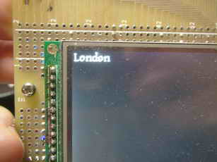 |
|
���ɁA�R���{�{�b�N�X����
�hAmerica�h��I�����đ��M���A
�ԐM�����X�g�{�b�N�X��
�@�@�@�@�@��M������� |
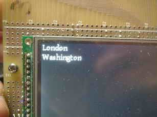 |
|
���ɁA�R���{�{�b�N�X����
�hJapan�h��I�����đ��M���A
�ԐM�����X�g�{�b�N�X��
�@�@�@�@�@��M������� |
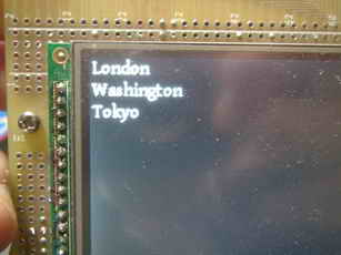 |
|
���ɁA�R���{�{�b�N�X����
�h�����h��I�����đ��M���A
�ԐM�����X�g�{�b�N�X��
�@�@�@�@�@��M������� |
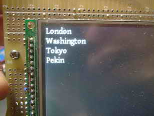 |
|
�Ō�ɁA�R���{�{�b�N�X����
�hI am a boy�h��I�����đ��M���A
�ԐM�����X�g�{�b�N�X��
�@�@�@�@�@��M������� |
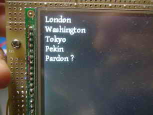 |
|
���@PIC32MX795F512L �@��HID�N���X�E�z�X�g���[�h���@�O���t�B�b�N�t���@ASSCII�����ȈՃG�f�B�^
�@�O���t�B�b�N�t���tPIC32MX795F512L�Ɂ@USB�R�l�N�^�̎s�̃L�[�{�[�h��ڑ������ꍇ�́@�ȒP�ȃG�f�B�^��������̂ŏЉ�܂��B
������i�d�l��
�@�EPIC32MX795F512L�ɃO���t�B�b�N�t����8080�@16�r�b�g�p�������Őڑ�����
�@�E�s�̂̓��{��109�L�[�{�[�h��ڑ����� �L�[�{�[�h����Ō����ĕ����ƋL�����O���t�B�b�N�t���ɕ\������
�@�E�O���t�B�b�N�ł̕����ɂ̓}�C�N���`�b�v��GDDX��Static Text �E�B�W�F�b�g��p����
�@�E�\���̑��Ɂ@�G���^�[�L�[�ł̉��s�@�y�уo�b�N�X�y�[�X�L�[�ƃf���[�g�L�[�ł̕����������ł��邱��
������i��H�}��(����H�}��PDF�t�@�C���j
�@ �@�@�@
������i�O�ρ����L�̎ʐ^�ɂ͏�L��H�}�ɂ͂Ȃ��A�܂��{�e�[�}�ƊW�̂Ȃ����i�����X�ʂ��Ă��܂�
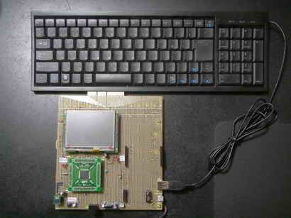
�@�@�@�@�@�@�@�@�@�@
�@���v���O�����၄
//Main( ).c
#include "Main.h"
#include "GDD_Screens.h"
#include <stdlib.h>
#include <string.h>
#include <stdio.h>
#include "GenericTypeDefs.h"
#include "HardwareProfile.h"
#include "usb_config.h"
#include "USB/usb.h"
#include "USB/usb_host_hid_parser.h"
#include "USB/usb_host_hid.h"
#include "1lcd_lib_C32.h"
#define STOP_TIMER_IN_IDLE_MODE 0x2000
#define TIMER_SOURCE_INTERNAL 0x0000
#define TIMER_ON 0x8000
#define GATED_TIME_DISABLED 0x0000
#define TIMER_16BIT_MODE 0x0000
#define TIMER_PRESCALER_1 0x0000
#define TIMER_PRESCALER_8 0x0010
#define TIMER_PRESCALER_64 0x0020
#define TIMER_PRESCALER_256 0x0030
#define TIMER_INTERRUPT_PRIORITY 0x0001
// Configuration bits
#pragma config FPLLODIV = DIV_1, FPLLMUL = MUL_20, FPLLIDIV = DIV_2, FWDTEN = OFF, FCKSM = CSECME, FPBDIV = DIV_1
#pragma config OSCIOFNC = ON, POSCMOD = XT, FSOSCEN = ON, FNOSC = PRIPLL
#pragma config CP = OFF, BWP = OFF, PWP = OFF
#pragma config UPLLEN = ON // USB PLL Enabled
#pragma config UPLLIDIV = DIV_2 // USB PLL Input Divider
typedef enum _APP_STATE
{
DEVICE_NOT_CONNECTED,
DEVICE_CONNECTED, /* Device Enumerated - Report Descriptor Parsed */
READY_TO_TX_RX_REPORT,
GET_INPUT_REPORT, /* perform operation on received report */
INPUT_REPORT_PENDING,
SEND_OUTPUT_REPORT, /* Not needed in case of mouse */
OUTPUT_REPORT_PENDING,
ERROR_REPORTED
} APP_STATE;
typedef struct _HID_REPORT_BUFFER
{
WORD Report_ID;
WORD ReportSize;
BYTE* ReportData;
WORD ReportPollRate;
} HID_REPORT_BUFFER;
typedef struct _HID_LED_REPORT_BUFFER
{
BYTE NUM_LOCK : 1;
BYTE CAPS_LOCK : 1;
BYTE SCROLL_LOCK : 1;
BYTE UNUSED : 5;
} HID_LED_REPORT_BUFFER;
#define MAX_ALLOWED_CURRENT (500) // Maximum power we can supply in mA
#define MINIMUM_POLL_INTERVAL (0x0A) // Minimum Polling rate for HID reports is 10ms
#define USAGE_PAGE_LEDS (0x08)
#define USAGE_PAGE_KEY_CODES (0x07)
#define USAGE_MIN_MODIFIER_KEY (0xE0)
#define USAGE_MAX_MODIFIER_KEY (0xE7)
#define USAGE_MIN_NORMAL_KEY (0x00)
#define USAGE_MAX_NORMAL_KEY (0xFF)
/* Array index for modifier keys */
#define MODIFIER_LEFT_CONTROL (0)
#define MODIFIER_LEFT_SHIFT (1)
#define MODIFIER_LEFT_ALT (2)
#define MODIFIER_LEFT_GUI (3)
#define MODIFIER_RIGHT_CONTROL (4)
#define MODIFIER_RIGHT_SHIFT (5)
#define MODIFIER_RIGHT_ALT (6)
#define MODIFIER_RIGHT_GUI (7)
#define HID_CAPS_LOCK_VAL (0x39)
#define HID_NUM_LOCK_VAL (0x53)
#define MAX_ERROR_COUNTER (10)
#define LCD_LINE_ONE (1)
#define LCD_LINE_TWO (2)
// macros to identify special charaters(other than Digits and Alphabets)
#define Symbol_Exclamation (0x1E)
#define Symbol_AT (0x1F)
#define Symbol_Pound (0x20)
#define Symbol_Dollar (0x21)
#define Symbol_Percentage (0x22)
#define Symbol_Cap (0x23)
#define Symbol_AND (0x24)
#define Symbol_Star (0x25)
#define Symbol_NormalBracketOpen (0x26)
#define Symbol_NormalBracketClose (0x27)
#define Symbol_Return (0x28)
#define Symbol_Escape (0x29)
#define Symbol_Backspace (0x2A)
#define Symbol_Tab (0x2B)
#define Symbol_Space (0x2C)
#define Symbol_HyphenUnderscore (0x2D)
#define Symbol_EqualAdd (0x2E)
#define Symbol_BracketOpen (0x2F)
#define Symbol_BracketClose (0x30)
#define Symbol_BackslashOR (0x31)
#define Symbol_SemiColon (0x33)
#define Symbol_InvertedComma (0x34)
#define Symbol_Tilde (0x35) //109�L�[�{�[�h�̊����E�S�p/���p�L�[�ƃo�e�B���O���Ă���
#define Symbol_CommaLessThan (0x36)
#define Symbol_PeriodGreaterThan (0x37)
#define Symbol_FrontSlashQuestion (0x38)
#define Symbol_Kanji (0x35)
#define Symbol_ScrLK (0x47)
#define Symbol_PrintScr (0x46)
#define Symbol_Delete (0x4C)
#define Symbol_PauseBreak (0x48)
//
APP_STATE App_State_Keyboard = DEVICE_NOT_CONNECTED;
HID_DATA_DETAILS Appl_LED_Indicator;
HID_DATA_DETAILS Appl_ModifierKeysDetails;
HID_DATA_DETAILS Appl_NormalKeysDetails;
HID_USER_DATA_SIZE Appl_BufferModifierKeys[8];
HID_USER_DATA_SIZE Appl_BufferNormalKeys[6];
HID_USER_DATA_SIZE Appl_ShadowBuffer1[6];
HID_REPORT_BUFFER Appl_raw_report_buffer;
HID_LED_REPORT_BUFFER Appl_led_report_buffer;
BYTE ErrorDriver;
BYTE ErrorCounter;
BYTE NumOfBytesRcvd;
BOOL ReportBufferUpdated;
BOOL LED_Key_Pressed = FALSE;
BOOL DisplayConnectOnce = FALSE;
BOOL DisplayDeatachOnce = FALSE;
BYTE CAPS_Lock_Pressed = 0;
BYTE NUM_Lock_Pressed = 0;
BYTE HeldKeyCount = 0;
BYTE HeldKey;
BYTE currCharPos;
BYTE FirstKeyPressed ;
// SPI Device Initialization Function
#if defined (USE_SST25VF016)
#define FlashInit(pInitData) SST25Init((DRV_SPI_INIT_DATA*)pInitData)
#if defined (SPI_CHANNEL_2_ENABLE)
const DRV_SPI_INIT_DATA SPI_Init_Data = {SST25_SPI_CHANNEL, 1, 0, 0, 1, 1, 0};
#endif
#endif
BYTE App_HID2ASCII(BYTE a); //convert USB HID code (buffer[2 to 7]) to ASCII code
void AppInitialize(void);
BOOL AppGetParsedReportDetails(void);
void App_Detect_Device(void);
void App_ProcessInputReport(void);
void App_PrepareOutputReport(void);
void InitializeTimer(void);
void App_Clear_Data_Buffer(void);
BOOL App_CompareKeyPressedPrevBuf(BYTE data);
void App_CopyToShadowBuffer(void);
BOOL USB_HID_DataCollectionHandler(void);
void LCD_Display_Routine(BYTE data, BYTE HIDData);
void ProcessIO(void);
char Buf[65]; //������̃o�b�t�@�[�p���W�X�^
volatile DWORD tick = 0; // tick counter
int myMode = 0;
int GLcdLineNum = 0; //�O���t�B�b�N�t���̍s��
unsigned char Kaigyou[] = "\n";
unsigned char tempBuf[1024];
unsigned char* myAllChar;
unsigned char tempBuf2[1024];
unsigned char* str20;
int myLineNum = 0; //�G�f�B�^�̏����ݍs�ԍ�(0-12)
int myColumnNum = -1; //�\�����镶���̗�ԍ�
int myCharPos = 0; //
int myColumnNum0 = 30;
// ���̃v���g�^�C�v�錾
void TickInit(void); // starts tick counter
//------------------------------------------------------------------------------
void delay_us(unsigned int usec) //1��sec�x����
{
int count;
count = (int)(Clock/20000000)*usec;
do //�����F�@at�@Clock=80000000
{ //delay_us(1000)��1003��sec�A�@delay_us(100)��102��sec�Adelay_us(10)��11��sec�Adelay_us(1)��1.6��sec
asm("NOP"); asm("NOP"); asm("NOP"); asm("NOP"); asm("NOP");
asm("NOP"); asm("NOP"); asm("NOP"); asm("NOP"); asm("NOP");
count--;
}while(count != 0);
}
//------------------------------------------------------------------------------
void delay_ms(unsigned int msec) //1msec�x����
{
unsigned int i;
for(i=0; i<msec; i++)
delay_us(1000);
}
int main(void)
{
INTEnableSystemMultiVectoredInt(); //�x�N�^�������荞�݂�������
SYSTEMConfigPerformance(GetSystemClock()); //SYSTEMConfigPerformance(80000000);// �V�X�e���œK��//�L���b�V���E�v���t�F�b�`�o�b�t�@�L����
DDPCONbits.JTAGEN = 0; //I/O�|�[�g�Ƃ���RA0�ARA1�ARA4�ARA5�������ꍇ�A�d��������DDPCON���W�X�^��bit3��0�ɁA�ݒ肷��K�v������G�܂��B
SYSTEMConfigWaitStatesAndPB( GetSystemClock() ); //�t���b�V����������PBCLK�f�o�C�_���w�肵���N���b�N�ōœK�ȏ�ԂɎ����I�ɐݒ�
CheKseg0CacheOn(); // Enable the cache for the best performance
AD1PCFG =0xFFFF; //���K�{ //B�|�[�g�F�A�i���O�@���@�f�W�^��
TRISBbits.TRISB15 = 0; //�L�����N�^�t���|�[�g�ݒ�
TRISBbits.TRISB14 = 0; //�L�����N�^�t���|�[�g�ݒ�
TRISBbits.TRISB13 = 0; //�L�����N�^�t���|�[�g�ݒ�
TRISBbits.TRISB12 = 0; //�L�����N�^�t���|�[�g�ݒ�
TRISAbits.TRISA9 = 0; //�L�����N�^�t���|�[�g�ݒ�
TRISAbits.TRISA10 = 0; //�L�����N�^�t���|�[�g�ݒ�
TRISGbits.TRISG15 = 0; //RG15(1�ԃs���j�|�[�g�@LED�_���p
TRISDbits.TRISD2 = 0; //RD2 LED�_���p
TRISDbits.TRISD3 = 0; //RD3 LED�_���p
LATGbits.LATG15 = 1; //LED off
LATDbits.LATD2 = 1; //LED off
LATDbits.LATD3 = 1; //LED off
TRISBbits.TRISB0 = 1; //RB0 in port
TRISBbits.TRISB1 = 1; //RB1 in port
lcd_init(); // LCD������
lcd_cmd(0b00001100); // �J�[�\��:OFF �u�ݸ:OFF
lcd_clear();
lcd_cmd(0x80); //1�ڂ̐擪��
sprintf(Buf,"USB & Touchi");//
lcd_str(Buf); //�t���\��
lcd_cmd(0xC0); //�Q�s�ڂ̐擪��
sprintf(Buf," Start !!"); //
lcd_str(Buf); // �J�n���b�Z�[�W1�s�ڕ\��
DisplayResetDisable(); //Sets RST high
DisplayResetConfig(); //Sets the pin to output
DelayMs(3000); //Wait 500 ms at startup
SetColor(BLACK);
ClearDevice();
GOL_MSG msg; // GOL message structure to interact with GOL
GOLInit(); // Initialize graphics library and create default style scheme for GOL
//SPI�t���b�V�������������� //Set IOs directions for SST25 SPI
//SST25VF016���Ȃ��Ɛ���ɕ\������Ȃ�
//��R����PI�̂�AD�R���o�[�^���g�p���āA�^�b�`�ʒu�����o����ꍇ�͈ʒu�Z���L���̂���SST25VF016�͕K�v
SST25_CS_LAT = 1;
SST25_CS_TRIS = 0;
SST25_SCK_TRIS = 0;
SST25_SDO_TRIS = 0;
SST25_SDI_TRIS = 1;
FlashInit(&SPI_Init_Data); // initialize the Flash Memory driver
USBInitialize(0); //USB�C�j�V�����C�Y
TouchHardwareInit(); //�^�b�`�p�l��������
TickInit(); //�^�C�}4 ������
GDDDemoCreateFirstScreen();
myAllChar = &tempBuf[0];
str20 = &tempBuf2[0];
while(1)
{
USBTasks();
ProcessIO();
if(GOLDraw()) // Draw GOL object
{
TouchGetMsg(&msg); // Get message from touch screen
GOLMsg(&msg); // Process message
}
}//end while
}
/////////////////////////////////////////////////////////////////////////////
// Function: WORD GOLMsgCallback(WORD objMsg, OBJ_HEADER* pObj, GOL_MSG* pMsg)
// Input: objMsg - translated message for the object,
// pObj - pointer to the object,
// pMsg - pointer to the non-translated, raw GOL message
// Output: if the function returns non-zero the message will be processed by default
// Overview: it's a user defined function. GOLMsg() function calls it each
// time the valid message for the object received
/////////////////////////////////////////////////////////////////////////////
WORD GOLMsgCallback(WORD objMsg, OBJ_HEADER *pObj, GOL_MSG *pMsg)
{
WORD objectID;
objectID = GetObjID(pObj);
GDDDemoGOLMsgCallback(objMsg, pObj, pMsg);
// Add additional code here...
return (1);
}
/////////////////////////////////////////////////////////////////////////////
// Function: WORD GOLDrawCallback()
// Output: if the function returns non-zero the draw control will be passed to GOL
// Overview: it's a user defined function. GOLDraw() function calls it each
// time when GOL objects drawing is completed. User drawing should be done here.
// GOL will not change color, line type and clipping region settings while
// this function returns zero.
/////////////////////////////////////////////////////////////////////////////
WORD GOLDrawCallback(void)
{
GDDDemoGOLDrawCallback();
// Add additional code here...
return (1);
}
void __ISR(_TIMER_4_VECTOR, ipl1) _T4Interrupt(void) //�^�C�}4���荞�� //100msec��
{
// LATGbits.LATG15 = 0; //���荞�ݎ��ԁi�����j�F3msec
tick++;
TMR4 = 0;
mT4ClearIntFlag(); // Clear flag
TouchDetectPosition();
/*
lcd_clear(); // �S����
lcd_cmd(0x80); //1�s�ڂ̐擪��
sprintf(Buf,"X = %d",TouchGetX());//�^�b�`X���W�\��
lcd_str(Buf); //�t���\��
lcd_cmd(0xC0); //�Q�s�ڂ̐擪��
sprintf(Buf,"Y = %d",TouchGetY()); //�^�b�`Y���W�\��
lcd_str(Buf); // �J�n���b�Z�[�W1�s�ڕ\��
*/
// LATGbits.LATG15 = 1;
}
//---------------------------------------------------------------------------------
#define SAMPLE_PERIOD 500 // us
#define TICK_PERIOD (GetPeripheralClock() * SAMPLE_PERIOD) / 4000000
//TICK_PERIOD = 80000000 * 500 / 4000000 = 80* 500 / 4 = 20*500 = 10000
void TickInit(void) //�^�C�}�S������
{
OpenTimer4(T4_ON | T4_PS_1_256, 31249); //1000/80000000*256*31249�@=99.9968 msec
// OpenTimer4(T4_ON | T4_PS_1_8, 10000); //2msec
// OpenTimer4(T4_ON | T4_PS_1_8, TICK_PERIOD); //�����l�F35��sec�@//�I�[�o�[�t���[�G���[����
ConfigIntTimer4(T4_INT_ON | T4_INT_PRIOR_1);
}
//---------------------------------------------------------------
void ProcessIO(void)
{
BYTE i;
App_Detect_Device();
switch(App_State_Keyboard)
{
case DEVICE_NOT_CONNECTED:
USBTasks();
if(DisplayDeatachOnce == FALSE)
{
lcd_clear();
lcd_cmd(0x80);
sprintf(Buf,"Device Det");
lcd_str(Buf);
// LCDDisplayString((BYTE*)"Device Detached ", LCD_LINE_ONE);
DisplayDeatachOnce = TRUE;
}
if(USBHostHID_ApiDeviceDetect()) /* True if report descriptor is parsed with no error */
{
App_State_Keyboard = DEVICE_CONNECTED;
DisplayConnectOnce = FALSE;
}
break;
case DEVICE_CONNECTED:
App_State_Keyboard = READY_TO_TX_RX_REPORT;
if(DisplayConnectOnce == FALSE)
{
lcd_clear();
lcd_cmd(0x80);
sprintf(Buf,"EX16 Boare ");//
lcd_str(Buf); //�t���\��
lcd_cmd(0xC0); //�Q�s�ڂ̐擪��
sprintf(Buf,"USB HIDHost Demo"); //
lcd_str(Buf); // �J�n���b�Z�[�W1�s�ڕ\��
#ifdef DEBUG_MODE
UART2PrintString( "Explorer16 Board \r\n" );
UART2PrintString( "USB HIDHost Demo \r\n" );
#endif
DisplayConnectOnce = TRUE;
DisplayDeatachOnce = FALSE;
}
InitializeTimer(); // start 10ms timer to schedule input reports
break;
case READY_TO_TX_RX_REPORT:
if(!USBHostHID_ApiDeviceDetect())
{
App_State_Keyboard = DEVICE_NOT_CONNECTED;
// DisplayOnce = FALSE;
}
break;
case GET_INPUT_REPORT:
if(USBHostHID_ApiGetReport(Appl_raw_report_buffer.Report_ID,Appl_ModifierKeysDetails.interfaceNum,
Appl_raw_report_buffer.ReportSize, Appl_raw_report_buffer.ReportData))
{
/* Host may be busy/error -- keep trying */
}
else
{
App_State_Keyboard = INPUT_REPORT_PENDING;
}
USBTasks();
break;
case INPUT_REPORT_PENDING:
if(USBHostHID_ApiTransferIsComplete(&ErrorDriver,&NumOfBytesRcvd))
{
if(ErrorDriver ||(NumOfBytesRcvd != Appl_raw_report_buffer.ReportSize ))
{
ErrorCounter++ ;
if(MAX_ERROR_COUNTER <= ErrorDriver)
App_State_Keyboard = ERROR_REPORTED;
else
App_State_Keyboard = READY_TO_TX_RX_REPORT;
}
else
{
ErrorCounter = 0;
ReportBufferUpdated = TRUE;
App_State_Keyboard = READY_TO_TX_RX_REPORT;
if(DisplayConnectOnce == TRUE)
{
for(i=0;i<Appl_raw_report_buffer.ReportSize;i++)
{
if(Appl_raw_report_buffer.ReportData[i] != 0)
{
lcd_clear();
lcd_cmd(0x80);
DisplayConnectOnce = FALSE;
}
}
}
App_ProcessInputReport(); //�L�[�{�[�h���͌��o�E�\��
App_PrepareOutputReport();
}
}
break;
case SEND_OUTPUT_REPORT: /* Will be done while implementing Keyboard */
if(USBHostHID_ApiSendReport(Appl_LED_Indicator.reportID,Appl_LED_Indicator.interfaceNum, Appl_LED_Indicator.reportLength,
(BYTE*)&Appl_led_report_buffer))
{
/* Host may be busy/error -- keep trying */
}
else
{
App_State_Keyboard = OUTPUT_REPORT_PENDING;
}
USBTasks();
break;
case OUTPUT_REPORT_PENDING:
if(USBHostHID_ApiTransferIsComplete(&ErrorDriver,&NumOfBytesRcvd))
{
if(ErrorDriver)
{
ErrorCounter++ ;
if(MAX_ERROR_COUNTER <= ErrorDriver)
App_State_Keyboard = ERROR_REPORTED;
// App_State_Keyboard = READY_TO_TX_RX_REPORT;
}
else
{
ErrorCounter = 0;
App_State_Keyboard = READY_TO_TX_RX_REPORT;
}
}
break;
case ERROR_REPORTED:
break;
default:
break;
}
}
/****************************************************************************
Function:
void App_PrepareOutputReport(void)
Description:
This function schedules output report if any LED indicator key is pressed.
Precondition:
None
Parameters:
None
Return Values:
None
Remarks:
None
***************************************************************************/
void App_PrepareOutputReport(void)
{
// if((READY_TO_TX_RX_REPORT == App_State_Keyboard) && (ReportBufferUpdated == TRUE))
if(ReportBufferUpdated == TRUE)
{
ReportBufferUpdated = FALSE;
if(LED_Key_Pressed)
{
App_State_Keyboard = SEND_OUTPUT_REPORT;
LED_Key_Pressed = FALSE;
}
}
}
/****************************************************************************
Function:
void App_ProcessInputReport(void)
Description:
This function processes input report received from HID device.
Precondition:
None
Parameters:
None
Return Values:
None
Remarks:
None
***************************************************************************/
void App_ProcessInputReport(void)
{
BYTE i;
BYTE data;
/* process input report received from device */
USBHostHID_ApiImportData(Appl_raw_report_buffer.ReportData, Appl_raw_report_buffer.ReportSize
,Appl_BufferModifierKeys, &Appl_ModifierKeysDetails);
USBHostHID_ApiImportData(Appl_raw_report_buffer.ReportData, Appl_raw_report_buffer.ReportSize
,Appl_BufferNormalKeys, &Appl_NormalKeysDetails);
for(i=0;i<(sizeof(Appl_BufferNormalKeys)/sizeof(Appl_BufferNormalKeys[0]));i++)
{
if(Appl_BufferNormalKeys[i] != 0)
{
if(Appl_BufferNormalKeys[i] == HID_CAPS_LOCK_VAL)
{
CAPS_Lock_Pressed = !CAPS_Lock_Pressed;
LED_Key_Pressed = TRUE;
Appl_led_report_buffer.CAPS_LOCK = CAPS_Lock_Pressed;
}else if(Appl_BufferNormalKeys[i] == HID_NUM_LOCK_VAL)
{
NUM_Lock_Pressed = !NUM_Lock_Pressed;
LED_Key_Pressed = TRUE;
Appl_led_report_buffer.NUM_LOCK = NUM_Lock_Pressed;
}else
{
/* check if key press was present in previous report */
// if key press was pressed in previous report neglect it ????
if(!App_CompareKeyPressedPrevBuf(Appl_BufferNormalKeys[i]))
{
//�A�X�L�[�R�[�h�ɕϊ�-----------------------------------------------------------------------------
data = App_HID2ASCII(Appl_BufferNormalKeys[i]); // convert data to ascii
LCD_Display_Routine(data,Appl_BufferNormalKeys[i] );
}
}
}
else
{
if(i==0)
{
HeldKeyCount = 0;
}
else
{
if(Appl_BufferNormalKeys[i-1] == HeldKey)
{
if(HeldKeyCount < 3)
{
HeldKeyCount++;
}
else
{
//�A�X�L�[�R�[�h�ɕϊ�-----------------------------------------------------------------------------
data = App_HID2ASCII(HeldKey); // convert data to ascii
LCD_Display_Routine(data,HeldKey );
}
}
else
{
HeldKeyCount = 0;
HeldKey = Appl_BufferNormalKeys[i-1];
}
}
break;
}
}
App_CopyToShadowBuffer();
App_Clear_Data_Buffer();
}
/****************************************************************************
Function:
void App_CopyToShadowBuffer(void)
Description:
This function updates the shadow buffers with previous reports.
Precondition:
None
Parameters:
None
Return Values:
None
Remarks:
None
***************************************************************************/
void App_CopyToShadowBuffer(void)
{
BYTE i;
for(i=0;i<(sizeof(Appl_BufferNormalKeys)/sizeof(Appl_BufferNormalKeys[0]));i++)
{
Appl_ShadowBuffer1[i] = Appl_BufferNormalKeys[i];
}
}
/****************************************************************************
Function:
BOOL App_CompareKeyPressedPrevBuf(BYTE data)
Description:
This function compares if the data byte received in report was sent in
previous report. This is to avoid duplication incase user key in strokes
at fast rate.
Precondition:
None
Parameters:
BYTE data - data byte that needs to be compared with previous
report
Return Values:
None
Remarks:
None
***************************************************************************/
BOOL App_CompareKeyPressedPrevBuf(BYTE data)
{
BYTE i;
for(i=0;i<(sizeof(Appl_BufferNormalKeys)/sizeof(Appl_BufferNormalKeys[0]));i++)
{
if(data == Appl_ShadowBuffer1[i])
{
return TRUE;
}
}
return FALSE;
}
/****************************************************************************
Function:
void App_Detect_Device(void)
Description:
This function monitors the status of device connected/disconnected
Precondition:
None
Parameters:
None
Return Values:
None
Remarks:
None
***************************************************************************/
void App_Detect_Device(void)
{
if(!USBHostHID_ApiDeviceDetect())
{
App_State_Keyboard = DEVICE_NOT_CONNECTED;
}
}
/****************************************************************************
Function:
void App_Clear_Data_Buffer(void)
Description:
This function clears the content of report buffer after reading
Precondition:
None
Parameters:
None
Return Values:
None
Remarks:
None
***************************************************************************/
void App_Clear_Data_Buffer(void)
{
BYTE i;
for(i=0;i<(sizeof(Appl_BufferNormalKeys)/sizeof(Appl_BufferNormalKeys[0]));i++)
{
Appl_BufferNormalKeys[i] = 0;
}
for(i=0;i<Appl_raw_report_buffer.ReportSize;i++)
{
Appl_raw_report_buffer.ReportData[i] = 0;
}
}
/****************************************************************************
Function:
BYTE App_HID2ASCII(BYTE a)
Description:
This function converts the HID code of the key pressed to coressponding
ASCII value. For Key strokes like Esc, Enter, Tab etc it returns 0.
Precondition:
None
Parameters:
BYTE a - HID code for the key pressed
Return Values:
BYTE - ASCII code for the key pressed
Remarks:
None
***************************************************************************/
BYTE App_HID2ASCII(BYTE a) //convert USB HID code (buffer[2 to 7]) to ASCII code
{
BYTE AsciiVal;
BYTE ShiftkeyStatus = 0;
if((Appl_BufferModifierKeys[MODIFIER_LEFT_SHIFT] == 1)||(Appl_BufferModifierKeys[MODIFIER_RIGHT_SHIFT] == 1))
{
ShiftkeyStatus = 1;
}
if(a>=0x1E && a<=0x27)
{
if(ShiftkeyStatus)
{
switch(a)
{
case Symbol_Exclamation: AsciiVal = 0x21;
break;
case Symbol_AT: AsciiVal = 0x40;
break;
case Symbol_Pound: AsciiVal = 0x23;
break;
case Symbol_Dollar: AsciiVal = 0x24;
break;
case Symbol_Percentage: AsciiVal = 0x25;
break;
case Symbol_Cap: AsciiVal = 0x5E;
break;
case Symbol_AND: AsciiVal = 0x26;
break;
case Symbol_Star: AsciiVal = 0x2A;
break;
case Symbol_NormalBracketOpen: AsciiVal = 0x28;
break;
case Symbol_NormalBracketClose: AsciiVal = 0x29;
break;
default:
break;
}
return(AsciiVal);
}
else
{
if(a==0x27)
{
return(0x30);
}
else
{
return(a+0x13);
}
}
}
if((a>=0x59 && a<=0x61)&&(NUM_Lock_Pressed == 1))
{
return(a-0x28);
}
if((a==0x62) &&(NUM_Lock_Pressed == 1)) return(0x30);
if(a>=0x04 && a<=0x1D)
{
if(((CAPS_Lock_Pressed == 1)&&((Appl_BufferModifierKeys[MODIFIER_LEFT_SHIFT] == 0)&&
(Appl_BufferModifierKeys[MODIFIER_RIGHT_SHIFT] == 0)))
||((CAPS_Lock_Pressed == 0)&&((Appl_BufferModifierKeys[MODIFIER_LEFT_SHIFT] == 1) ||
(Appl_BufferModifierKeys[MODIFIER_RIGHT_SHIFT] == 1))))
return(a+0x3d); /* return capital */
else
return(a+0x5d); /* return small case */
}
if(a>=0x2D && a<=0x38)
{
switch(a)
{
case Symbol_HyphenUnderscore:
if(!ShiftkeyStatus)
AsciiVal = 0x2D;
else
AsciiVal = 0x5F;
break;
case Symbol_EqualAdd:
if(!ShiftkeyStatus)
AsciiVal = 0x3D;
else
AsciiVal = 0x2B;
break;
case Symbol_BracketOpen:
if(!ShiftkeyStatus)
AsciiVal = 0x5B;
else
AsciiVal = 0x7B;
break;
case Symbol_BracketClose:
if(!ShiftkeyStatus)
AsciiVal = 0x5D;
else
AsciiVal = 0x7D;
break;
case Symbol_BackslashOR:
if(!ShiftkeyStatus)
AsciiVal = 0x5C;
else
AsciiVal = 0x7C;
break;
case Symbol_SemiColon:
if(!ShiftkeyStatus)
AsciiVal = 0x3B;
else
AsciiVal = 0x3A;
break;
case Symbol_InvertedComma:
if(!ShiftkeyStatus)
AsciiVal = 0x27;
else
AsciiVal = 0x22;
break;
case Symbol_Tilde:
if(!ShiftkeyStatus)
AsciiVal = 0x60;
else
AsciiVal = 0x7E;
break;
case Symbol_CommaLessThan:
if(!ShiftkeyStatus)
AsciiVal = 0x2C;
else
AsciiVal = 0x3C;
break;
case Symbol_PeriodGreaterThan:
if(!ShiftkeyStatus)
AsciiVal = 0x2E;
else
AsciiVal = 0x3E;
break;
case Symbol_FrontSlashQuestion:
if(!ShiftkeyStatus)
AsciiVal = 0x2F;
else
AsciiVal = 0x3F;
break;
default:
break;
}
return(AsciiVal);
}
return(0);
}
/****************************************************************************
Function:
void LCD_Display_Routine(BYTE data , BYTE HIDData)
Description:
This function displays the key strokes on the LCD mounted on Explorer16
demo board.
Precondition:
None
Parameters:
BYTE data - ASCII code for the key pressed
BYTE HIDData - HID code for the key pressed, this is needed to take
action for keys like Esc, Enter, Tab etc.
Return Values:
None
Remarks:
***************************************************************************/
void LCD_Display_Routine(BYTE data , BYTE HIDData)
{
BYTE LineNum;
BYTE CharPos;
int i;
LineNum = ((currCharPos & 0x30) >> 4);
CharPos = currCharPos & 0x0F;
if(((HIDData>=0x1E && HIDData<=0x27) || (HIDData>=0x04 && HIDData<=0x1D) ||
(HIDData>=0x2D && HIDData<=0x38) ||
((HIDData>=0x59 && HIDData<=0x62)&&(NUM_Lock_Pressed == 1))) && (HIDData != 0x35)) //0x35: �����L�[�lj�
{
lcd_data(data);
currCharPos++;
if(myColumnNum == (myColumnNum0 - 1))
{
strncat(myAllChar,Kaigyou,16); //���s�L��\n �lj�
myCharPos++;
myColumnNum = 0; //��ԍ����Z�b�g
myLineNum++;
if(myLineNum == 13)
{
//�O���t�B�b�N�t����Static Text Widget�ɕ\��
STATICTEXT *pSTE_1 = (STATICTEXT*)GOLFindObject(STE_1); //�G�f�B�b�g�{�b�N�X�̃I�u�W�F�N�g���o
pSTE_1->hdr.state = ST_DRAW; //�ĕ`��ɂ�蕶���͍��A���C���Ƀ��Z�b�g�����
for(i = 0; i <1024; i++)tempBuf[i] = 0x00;
StSetText((STATICTEXT*)pSTE_1, myAllChar); //
SetState(pSTE_1, ST_DRAW);
}
}
sprintf(Buf,"%c",data);
myCharPos++;
myColumnNum++;
}
else if(HIDData == 0x29) // escape key pressed
{
lcd_clear();
lcd_cmd(0x80);
currCharPos = 0;
// sprintf(Buf,"HID = 0x%x, Key = ESC",HIDData,data,data);
}
else if (HIDData == 0x2C) //�X�y�[�X�������ꂽ�ꍇ
{
lcd_data(0x20); // /0x20: �A�X�L�[�����̃X�y�[�X
currCharPos++;
data = 0x20;
sprintf(Buf,"%c",data);
myCharPos++;
}
else if (HIDData == Symbol_Backspace) //�o�b�N�X�y�[�X�������ꂽ�ꍇ
{
if(currCharPos != 0)
{
lcd_cmd(0b00010000);
lcd_data(0x20); // space ascii value 0x20
lcd_cmd(0b00010000);
currCharPos--;
}
sprintf(Buf,"%c",0x00); //0x20: �A�X�L�[�����̃X�y�[�X
myCharPos--;
myColumnNum--;
if(myColumnNum < 0)
{
myColumnNum = myColumnNum0;
myLineNum--;
}
if(tempBuf[myCharPos] == '\n')myCharPos--;
tempBuf[myCharPos] = 0x00; //������I�[�L��\0���Z�b�g
}
else if((HIDData>=0x4F && HIDData<=0x52) ||
(( HIDData==0x5C || HIDData==0x5E || HIDData==0x5A || HIDData==0x60 )
&& (NUM_Lock_Pressed == 0)))
{
switch(HIDData)
{
case 0x4F : // Right Arrow
case 0x5E :
lcd_cmd(0b00010100);
currCharPos++;
sprintf(Buf,"HID = 0x%x, Key = Right Arrow",HIDData,data,data);
break;
case 0x50 : // Left Arrow
case 0x5C :
lcd_cmd(0b00010000);
currCharPos--;
sprintf(Buf,"HID = 0x%x, Key = Left Arrow",HIDData,data,data);
break;
case 0x52 : // Up Arrow
case 0x60 :
if(LineNum == 1)
{
// LCDShiftCursorUp(); //�Ή�������Ȃ�
currCharPos = currCharPos - 16;
LineNum = 0;
}
sprintf(Buf,"HID = 0x%x, Key = Up Arrow",HIDData,data,data);
break;
case 0x51 : // Down Arrow
case 0x5A :
if(LineNum == 0)
{
// LCDShiftCursorDown(); //�Ή�������Ȃ�
currCharPos = currCharPos + 16;
LineNum = 1;
}
sprintf(Buf,"HID = 0x%x, Key = Down Arrow",HIDData,data,data);
break;
default :
break;
}
}
else if(HIDData == Symbol_Return)
{
sprintf(Buf,"\n");
myCharPos++;
myColumnNum = 0;
myLineNum++;
if(myLineNum == 13)
{
//�O���t�B�b�N�t����Static Text Widget�ɕ\��
STATICTEXT *pSTE_1 = (STATICTEXT*)GOLFindObject(STE_1); //�G�f�B�b�g�{�b�N�X�̃I�u�W�F�N�g���o
pSTE_1->hdr.state = ST_DRAW; //�ĕ`��ɂ�蕶���͍��A���C���Ƀ��Z�b�g�����
for(i = 0; i <1024; i++)tempBuf[i] = 0x00;
StSetText((STATICTEXT*)pSTE_1, myAllChar); //
SetState(pSTE_1, ST_DRAW);
}
// sprintf(Buf,"HID = 0x%x, Key = Return",HIDData,data,data);
}
else if(HIDData == Symbol_Kanji)
{
// sprintf(Buf,"HID = 0x%x, Key = Kanji",HIDData,data,data);
}
else if(HIDData == Symbol_Tab)
{
// sprintf(Buf,"HID = 0x%x, Key = Tab",HIDData,data,data);
}
else if(HIDData == Symbol_Delete)
{
// sprintf(Buf,"HID = 0x%x, Key = Delete",HIDData,data,data);
}
else if(HIDData == Symbol_PrintScr)
{
// sprintf(Buf,"HID = 0x%x, Key = PrintScr",HIDData,data,data);
}
else if(HIDData == Symbol_PauseBreak)
{
// sprintf(Buf,"HID = 0x%x, Key = PauseBreak",HIDData,data,data);
}
else if(HIDData == Symbol_ScrLK)
{
// sprintf(Buf,"HID = 0x%x, Key = ScrLK",HIDData,data,data);
}
else
{
sprintf(Buf,"HID = 0x%x, Key = ?",HIDData,data,data);
}
//�O���t�B�b�N�t����Static Text Widget�ɕ\��
STATICTEXT *pSTE_1 = (STATICTEXT*)GOLFindObject(STE_1); //�G�f�B�b�g�{�b�N�X�̃I�u�W�F�N�g���o
pSTE_1->hdr.state = ST_DRAW; //�ĕ`��ɂ�蕶���͍��A���C���Ƀ��Z�b�g�����
strncat(myAllChar,Buf,65); //�����lj�
StSetText((STATICTEXT*)pSTE_1, myAllChar); //
SetState(pSTE_1, ST_DRAW);
LineNum = ((currCharPos & 0x30) >> 4);
CharPos = currCharPos & 0x0F;
if((LineNum == 1) && (CharPos == 0x0))
{
lcd_cmd(0xC0);
currCharPos = 0x10;
}else if((LineNum == 2) && (CharPos == 0x0))
{
lcd_clear();
lcd_cmd(0x80);
currCharPos = 0;
}
if(currCharPos > 0x20)
{
lcd_clear();
lcd_cmd(0x80);
currCharPos = 0;
}
}
/****************************************************************************
Function:
BOOL USB_HID_DataCollectionHandler(void)
Description:
This function is invoked by HID client , purpose is to collect the
details extracted from the report descriptor. HID client will store
information extracted from the report descriptor in data structures.
Application needs to create object for each report type it needs to
extract.
For ex: HID_DATA_DETAILS Appl_ModifierKeysDetails;
HID_DATA_DETAILS is defined in file usb_host_hid_appl_interface.h
Each member of the structure must be initialized inside this function.
Application interface layer provides functions :
USBHostHID_ApiFindBit()
USBHostHID_ApiFindValue()
These functions can be used to fill in the details as shown in the demo
code.
Precondition:
None
Parameters:
None
Return Values:
TRUE - If the report details are collected successfully.
FALSE - If the application does not find the the supported format.
Remarks:
This Function name should be entered in the USB configuration tool
in the field "Parsed Data Collection handler".
If the application does not define this function , then HID cient
assumes that Application is aware of report format of the attached
device.
***************************************************************************/
BOOL USB_HID_DataCollectionHandler(void)
{
BYTE NumOfReportItem = 0;
BYTE i;
USB_HID_ITEM_LIST* pitemListPtrs;
USB_HID_DEVICE_RPT_INFO* pDeviceRptinfo;
HID_REPORTITEM *reportItem;
HID_USAGEITEM *hidUsageItem;
BYTE usageIndex;
BYTE reportIndex;
BOOL foundLEDIndicator = FALSE;
BOOL foundModifierKey = FALSE;
BOOL foundNormalKey = FALSE;
pDeviceRptinfo = USBHostHID_GetCurrentReportInfo(); // Get current Report Info pointer
pitemListPtrs = USBHostHID_GetItemListPointers(); // Get pointer to list of item pointers
BOOL status = FALSE;
/* Find Report Item Index for Modifier Keys */
/* Once report Item is located , extract information from data structures provided by the parser */
NumOfReportItem = pDeviceRptinfo->reportItems;
for(i=0;i<NumOfReportItem;i++)
{
reportItem = &pitemListPtrs->reportItemList[i];
if((reportItem->reportType==hidReportInput) && (reportItem->dataModes == HIDData_Variable)&&
(reportItem->globals.usagePage==USAGE_PAGE_KEY_CODES))
{
/* We now know report item points to modifier keys */
/* Now make sure usage Min & Max are as per application */
usageIndex = reportItem->firstUsageItem;
hidUsageItem = &pitemListPtrs->usageItemList[usageIndex];
if((hidUsageItem->usageMinimum == USAGE_MIN_MODIFIER_KEY)
&&(hidUsageItem->usageMaximum == USAGE_MAX_MODIFIER_KEY)) //else application cannot suuport
{
reportIndex = reportItem->globals.reportIndex;
Appl_ModifierKeysDetails.reportLength = (pitemListPtrs->reportList[reportIndex].inputBits + 7)/8;
Appl_ModifierKeysDetails.reportID = (BYTE)reportItem->globals.reportID;
Appl_ModifierKeysDetails.bitOffset = (BYTE)reportItem->startBit;
Appl_ModifierKeysDetails.bitLength = (BYTE)reportItem->globals.reportsize;
Appl_ModifierKeysDetails.count=(BYTE)reportItem->globals.reportCount;
Appl_ModifierKeysDetails.interfaceNum= USBHostHID_ApiGetCurrentInterfaceNum();
foundModifierKey = TRUE;
}
}
else if((reportItem->reportType==hidReportInput) && (reportItem->dataModes == HIDData_Array)&&
(reportItem->globals.usagePage==USAGE_PAGE_KEY_CODES))
{
/* We now know report item points to modifier keys */
/* Now make sure usage Min & Max are as per application */
usageIndex = reportItem->firstUsageItem;
hidUsageItem = &pitemListPtrs->usageItemList[usageIndex];
if((hidUsageItem->usageMinimum == USAGE_MIN_NORMAL_KEY)
&&(hidUsageItem->usageMaximum <= USAGE_MAX_NORMAL_KEY)) //else application cannot suuport
{
reportIndex = reportItem->globals.reportIndex;
Appl_NormalKeysDetails.reportLength = (pitemListPtrs->reportList[reportIndex].inputBits + 7)/8;
Appl_NormalKeysDetails.reportID = (BYTE)reportItem->globals.reportID;
Appl_NormalKeysDetails.bitOffset = (BYTE)reportItem->startBit;
Appl_NormalKeysDetails.bitLength = (BYTE)reportItem->globals.reportsize;
Appl_NormalKeysDetails.count=(BYTE)reportItem->globals.reportCount;
Appl_NormalKeysDetails.interfaceNum= USBHostHID_ApiGetCurrentInterfaceNum();
foundNormalKey = TRUE;
}
}
else if((reportItem->reportType==hidReportOutput) &&
(reportItem->globals.usagePage==USAGE_PAGE_LEDS))
{
usageIndex = reportItem->firstUsageItem;
hidUsageItem = &pitemListPtrs->usageItemList[usageIndex];
reportIndex = reportItem->globals.reportIndex;
Appl_LED_Indicator.reportLength = (pitemListPtrs->reportList[reportIndex].outputBits + 7)/8;
Appl_LED_Indicator.reportID = (BYTE)reportItem->globals.reportID;
Appl_LED_Indicator.bitOffset = (BYTE)reportItem->startBit;
Appl_LED_Indicator.bitLength = (BYTE)reportItem->globals.reportsize;
Appl_LED_Indicator.count=(BYTE)reportItem->globals.reportCount;
Appl_LED_Indicator.interfaceNum= USBHostHID_ApiGetCurrentInterfaceNum();
foundLEDIndicator = TRUE;
}
}
if(pDeviceRptinfo->reports == 1)
{
Appl_raw_report_buffer.Report_ID = 0;
Appl_raw_report_buffer.ReportSize = (pitemListPtrs->reportList[reportIndex].inputBits + 7)/8;
Appl_raw_report_buffer.ReportData = (BYTE*)malloc(Appl_raw_report_buffer.ReportSize);
Appl_raw_report_buffer.ReportPollRate = pDeviceRptinfo->reportPollingRate;
if((foundNormalKey == TRUE)&&(foundModifierKey == TRUE))
status = TRUE;
}
return(status);
}
/****************************************************************************
Function:
void InitializeTimer( void )
Description:
This function initializes the tick timer. It configures and starts the
timer, and enables the timer interrupt.
Precondition:
None
Parameters:
None
Returns:
None
Remarks:
None
***************************************************************************/
void InitializeTimer( void ) //�^�C�}4�@���@�^�C�}5�ɕύX�@//GDDX�̃C���^�[�o���^�C�}�i�^�C�}4�j�ƃo�b�e�B���O����@
{
//TODO - PIC32 support
T5CON = 0x0; //Stop and Init Timer
// T4CON = 0x0; //Stop and Init Timer
T5CON = 0x0060;
// T4CON = 0x0060;
//prescaler=1:64,
//internal clock
TMR5 = 0; //Clear timer register
// TMR4 = 0; //Clear timer register
PR5 = 0x7FFF; //Load period register
//PR4 = 0x7FFF; //Load period register
//1000/80000000*64*0x7FFF(32767) = 26.2msec
// OpenTimer4(T4_ON | T4_PS_1_256, 31249); //1000/80000000*256*31249�@=99.9968 msec
IPC5SET = 0x00000004; // Set priority level=1 and
// IPC4SET = 0x00000004; // Set priority level=1 and
IPC5SET = 0x00000001; // Set subpriority level=1
// IPC4SET = 0x00000001; // Set subpriority level=1
// Could have also done this in single
// operation by assigning IPC5SET = 0x00000005
// IFS0CLR = 0x00010000; // Clear the Timer5 interrupt status flag
// IEC0SET = 0x00010000; // Enable Timer5 interrupts
IFS0bits.T5IF = 0;
// IFS0bits.T4IF = 0;
IEC0bits.T5IE = 1;
// IEC0bits.T4IE = 1;
T5CONSET = 0x8000;//Start Timer
// T4CONSET = 0x8000;//Start Timer
return;
}
/****************************************************************************
Function:
void __attribute__((__interrupt__, auto_psv)) _T3Interrupt(void)
Description:
Timer ISR, used to update application state. If no transfers are pending
new input request is scheduled.
Precondition:
None
Parameters:
None
Return Values:
None
Remarks:
None
***************************************************************************/
#pragma interrupt _T5Interrupt ipl4 vector 20 //�^�C�}5 //�����݃��x���F4�@//�x�N�^�[�ԍ��F20
//#pragma interrupt _T4Interrupt ipl4 vector 16
void _T5Interrupt(void)
//void _T4Interrupt( void )
{
if(myMode == 0)
{
myMode = 1;
LATDbits.LATD3 = 0;
}
else
{
myMode = 0;
LATDbits.LATD3 = 1;
}
if (IFS0bits.T5IF)
// if (IFS0bits.T4IF)
{
IFS0bits.T5IF = 0;
// IFS0bits.T4IF = 0;
if(READY_TO_TX_RX_REPORT == App_State_Keyboard)
{
App_State_Keyboard = GET_INPUT_REPORT; // If no report is pending schedule new request
}
}
}
// USB Support Functions
BOOL USB_ApplicationEventHandler( BYTE address, USB_EVENT event, void *data, DWORD size )
{
switch( (INT)event )
{
case EVENT_VBUS_REQUEST_POWER:
// The data pointer points to a byte that represents the amount of power
// requested in mA, divided by two. If the device wants too much power,
// we reject it.
if (((USB_VBUS_POWER_EVENT_DATA*)data)->current <= (MAX_ALLOWED_CURRENT / 2))
{
return TRUE;
}
else
{
UART2PrintString( "\r\n***** USB Error - device requires too much current *****\r\n" );
}
break;
case EVENT_VBUS_RELEASE_POWER:
// Turn off Vbus power.
// The PIC24F with the Explorer 16 cannot turn off Vbus through software.
return TRUE;
break;
case EVENT_HUB_ATTACH:
UART2PrintString( "\r\n***** USB Error - hubs are not supported *****\r\n" );
return TRUE;
break;
case EVENT_UNSUPPORTED_DEVICE:
UART2PrintString( "\r\n***** USB Error - device is not supported *****\r\n" );
return TRUE;
break;
case EVENT_CANNOT_ENUMERATE:
UART2PrintString( "\r\n***** USB Error - cannot enumerate device *****\r\n" );
return TRUE;
break;
case EVENT_CLIENT_INIT_ERROR:
UART2PrintString( "\r\n***** USB Error - client driver initialization error *****\r\n" );
return TRUE;
break;
case EVENT_OUT_OF_MEMORY:
UART2PrintString( "\r\n***** USB Error - out of heap memory *****\r\n" );
return TRUE;
break;
case EVENT_UNSPECIFIED_ERROR: // This should never be generated.
UART2PrintString( "\r\n***** USB Error - unspecified *****\r\n" );
return TRUE;
break;
case EVENT_HID_RPT_DESC_PARSED:
#ifdef APPL_COLLECT_PARSED_DATA
return(APPL_COLLECT_PARSED_DATA());
#else
return TRUE;
#endif
break;
default:
break;
}
return FALSE;
}
//���̑��@FAT�A�O���t�B�b�N���C�u�����֘A�̃C���N���[�h�t�@�C���͉��L�ɂ���܂��B
//�}�C�N���`�b�v�̃��C�u�����_�E�����[�h�y�[�W�F�@Microchip Libraries for Applications�@�@�����������o�[�W�����́@\microchip_solutions_v2013-02-15�@�ł��B
//GDDX�֘A�̃t�@�C���́@Microchip Graphics Display Designer X�@����_�E�����[�h�ł��܂��B�@�����������o�[�W�����́@GDDX v.1.10�@�ł�
//�O���t�B�b�N�t��INT035TFT�̊֘A���́@Displaytech�̃z�[���y�[�W�@�y�с@Displaytech��Forum�@ �ɂ���܂��B
�����s���ʁ�
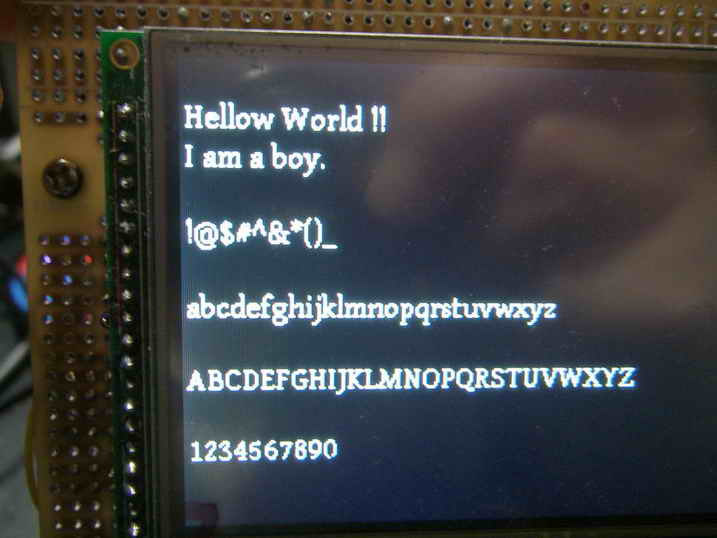
�@
�@���v���O�����၄
main()
{
}
�@
�@�@�@�@�@

